Arduino how to connect a joystick to a servo machine. Arduino joystick - connection and sketch. Connecting a joystick to Arduino UNO
There are analog joystick modules for Arduino boards. As a rule, they have an X, Y axis and a button - the Z axis. The joystick allows you to more smoothly and accurately monitor the degree of deviation from the zero point. And in addition to being more convenient than buttons, this allows you to implement more advanced interfaces. For example, when changing a value in the menu, you can write a program in such a way that the more the joystick axis is deflected, the faster the value of the variable changes. For example, we need to change the value from 0 to 2000 in steps of 1. Imagine how many times you would need to press a button or write a special algorithm, say, if the press lasts for more than 3 seconds, add change the step by 10 or 100. And when using a joystick, this can be done much easier to implement.
The average price for such modules fluctuates around $1-2 per module (with free delivery to Russia). Search for modules in the AliExpress store
The modules themselves look something like this:
Don't be intimidated by the number of pins, this is done for versatility and ease of connection. The Vcc and GND pins between all three groups of pins are connected. That. To connect you need 5 wires: X axis, Y axis, Z button, V cc power and common GND. Joysticks are passive modules and do not consume any power from the Arduino board. The V cc supply is only needed for the pull-up resistors. There are modules without pull-up resistors, in which case it is necessary to pull the button connection pin to +V cc through a 1-10 kOhm resistor.
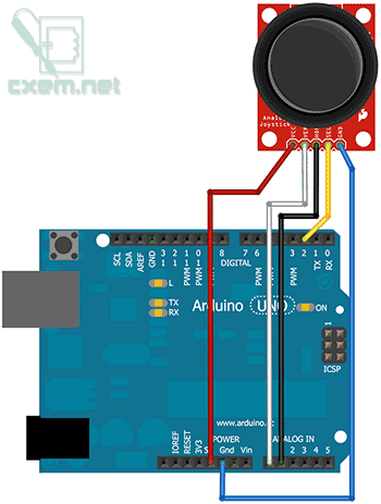
Connection diagram to Arduino:
In the program, working with the joystick is also very simple:
#define axis_X 0 // X Axis is connected to Analog 0 #define axis_Y 1 // Y Axis is connected to Analog 1 #define axis_Z 2 // Z Axis (joystick button) is connected to Digital 2 int value_X, value_Y, value_Z = 0; // Variables for storing axis values void setup() ( pinMode(axis_Z, INPUT); // Set as input Serial.begin(9600); ) void loop() ( value_X = analogRead(axis_X); // Read the analog axis value X Serial.print("X:"); Serial.print(value_X, DEC); // Output the value to Serial Monitor value_Y = analogRead(axis_Y); // Read the analog value of the Y axis Serial.print(" | Y:" ); Serial.print(value_Y, DEC); // Display the value in Serial Monitor value_Z = digitalRead(axis_Z); // Read the digital value of the Z axis (button) value_Z = value_Z ^ 1; // Invert the value Serial.print(" | Z: "); Serial.println(value_Z, DEC); // Output the value to Serial Monitor delay(250); // Delay 250 ms)
As you can see above, at the beginning we define the input pins for the axes (define), and then in the main loop we read the values from the pins and output them to the Serial Monitor. And we see the following picture:

As you can see, everything is quite simple. And finally, we will write a small program, the purpose of which will be to change the value of the variable, depending on the deviation of the joystick along the Y axis from the zero point. And when you press the joystick button, the variable will be reset.
#define axis_Y 1 // Y axis is connected to Analog 1 #define axis_Z 2 // Z axis (joystick button) is connected to Digital 2 int value, value_Y, value_Z = 0; // Variables for storing axis values void setup() ( pinMode(axis_Z, INPUT); // Set as input Serial.begin(9600); ) void loop() ( value_Y = analogRead(axis_Y); // Read the analog axis value Y if(value_Y >= 0 && value_Y< 100) value = value - 10; if(value_Y >100 && value_Y< 300) value = value - 5; if(value_Y >300 && value_Y< 520) value = value - 1; if(value_Y >535 && value_Y< 700) value = value + 1; if(value_Y >700 && value_Y< 900) value = value + 5; if(value_Y >900) value = value + 10;

value_Z = digitalRead(axis_Z); // Read the digital value of the Z axis (button) if(value_Z == 0) value = 0; // Reset the value Serial.println(value, DEC); // Output the value to Serial Monitor delay(500); // Delay )
Homemade assembly process:
Step one. Connecting servomotors

The process of assembling a homemade product begins with connecting servomotors. In order to assemble a preliminary layout, a circuit board is used. Then you can make a separate shield. In the picture you can see exactly how everything is connected.
The red cable is power, it connects to the 5V pin on the Arduino controller.
The yellow cable from the Right & Left servomotor must be connected to pin 11. On some models it may be white.
A similar yellow Up & Down cable must be connected to pin 4. It may also be white on some engine models.
It is important to remember that the signal connectors that control the motor come from the PWM outputs.
Step two. Connecting the joystick
You can see how the joystick is connected in the picture. At first, the scheme may seem quite complicated, but in fact there is nothing complicated here. As with motors, a circuit board is used for connection.

1. On the joystick module you can find U/R+ and L/R+ outputs. Power is connected through these outputs. Accordingly, you need to apply +5V voltage here from the corresponding pin on the Arduino.
2. The joystick also has two connectors called L/R and two U/D connectors. They need to be connected to analog outputs A3 and A4.
3. Well, in conclusion, the ground on the joystick needs to be connected to the ground on the Arduino.
After assembly, the connection must be rechecked. It is connection errors that cause problems in most cases. This is especially true when a circuit board is used and there are many connections on it.
Step three. Sketch for Arduino
The code is very simple and contains detailed comments. The above code just needs to be copied into the Arduino IDE. Once the code is loaded, the motors should not move. They should only start moving when you press a button on the joystick.

Problems that may arise and ways to solve them
1. If the engines do not turn on, you need to recheck the connection. PWM type outputs are used to connect motors, and analog outputs are used to connect joysticks.
2. It happens that immediately after loading the code, the engines begin to vibrate. This happens if you connect the U/D+ L/R+ pins incorrectly. The connection must be checked carefully. To avoid burning the board during testing, it must be disconnected from the computer.
3. If everything has been rechecked, but the motors still do not want to work, you can try reconnecting the joystick. It needs to be removed from the circuit board and then installed back with some force. The joystick connectors should fit well into the breadboard.
If everything worked out, you can now start creating some homemade products with joystick control. For example, you can make a robot that can be controlled using a joystick, and much more.
Is a data input module. With its help you can control robots, manipulators, machine tools, various models(cars, tanks, airplanes, helicopters, quadcopters, boats, etc.), and also used to create game consoles, select menu items on displays and indicators, enter values, etc. The joystick can not only be moved along the X and Y axes, but also pressed.
Video:
Specification:
- Supply voltage: 5 V / 3.3 V (both voltages are within the acceptable range).
- Current consumption:< 10 мА
- Dimensions: 30x30 mm
All modules of the "Trema" line are made in the same format
Connection:
- The “X” and “Y” pins of the module are connected to any analog inputs of the Arduino. The values read from these pins increase as you move the joystick from left to right and from bottom to top.
- The "K" pin is digital and connects to any Arduino pin. In the normal state, it has a logical level of “0”, and when you press the joystick, it changes to a logical “1”.
- The "V" and "G" pins are the power pins.
It is convenient to connect the module in 3 ways, depending on the situation:
Method - 1: Using a wired cable and Piranha UNO
Using the “Father - Mom” wires, we connect directly to the Piranha UNO controller

Method - 2: Using Trema Set Shield
The module can be connected to any of the Trema Set Shield's analog inputs.

Method - 3: Using a wired cable and Shield
Using a 5-wire cable to Trema Shield, Trema-Power Shield, Motor Shield, Trema Shield NANO, etc.

Nutrition:
Input voltage 5V or 3.3V direct current, is supplied to the Vcc (V) and GND (G) pins.
More details about the module:
The module data is read from two potentiometers and a tact button, mechanically connected to the joystick lever. The button is connected to the Vcc power supply and the “K” output, which is pressed to GND through a resistor. Consequently, only two states can be set at the “K” output: logical “0” (the button is released) or “1” (the button is pressed). The “X” and “Y” coordinate pins are analog outputs of the module; they are connected to potentiometers so that the voltage removed between these pins and GND increases when the joystick is moved from left to right and from bottom to top.
Examples:
Detecting the joystick position and turning on the LED by pressing a button
const int8_t Xaxis = A0; // Determine the pin number to which the joystick's X-axis contact is connected const int8_t Yaxis = A1; // Determine the pin number to which the joystick axis contact is connected const int8_t Button = 2; // Determine the pin number to which the joystick button contact is connected const int8_t LED = 7; // Determine the pin number to which the LED is connected uint16_t XborderMIN = 505; // Set the value boundary, BELOW which it will be considered that the joystick is tilted along the X axis to the left uint16_t XborderMAX = 515; // Set the value boundary, HIGHER which it will be considered that the joystick is tilted along the X axis to the right uint16_t YborderMIN = 505; // Set the value boundary, BELOW which it will be considered that the joystick is deflected down the Y axis uint16_t YborderMAX = 515; // Set the value limit, ABOVE which it will be considered that the joystick is deflected upward along the Y axis uint16_t Xvol = 0, Yvol = 0; // Set variables that will take values read from the joystick axes void setup() ( Serial.begin(9600); // Initiate data transfer to the serial port monitor pinMode(LED, OUTPUT); // Set up the LED output to work in output mode pinMode(Button, INPUT); // Set the Button pin to work in input mode) void loop() ( Xvol = analogRead(Xaxis); // Read the X-axis values Yvol = analogRead(Yaxis); // Read the axis values If (Xvol< XborderMIN) { // Проверяем, полученное значение Х меньше нижней границы центрального положения или нет. Если да, то if (Yvol < YborderMIN) { // проверяем, полученное значение У меньше нижней границы центрального положения или нет. Если да, то Serial.println("Left-Down"); // значит джойстик находится в положении ВЛЕВО-ВНИЗ } else if (Yvol >YborderMAX) ( // If the resulting value Y is greater than the upper limit of the central position, then Serial.println("Left-Up"); // means the joystick is in the LEFT-UP position ) else ( Serial.println("Left"); // If the received value Y is within the boundaries of the central position along the Y axis, then the joystick is deflected to the LEFT ) ) else if (Xvol > XborderMAX) ( // Check whether the received value X is greater than the upper limit of the central position or not. If so, then if (Yvol< YborderMIN) { // проверяем, полученное значение У меньше нижней границы центрального положения или нет. Если да, то Serial.println("Right-Down"); // значит джойстик находится в положении ВПРАВО-ВНИЗ } else if (Yvol >YborderMAX) ( // If the resulting value Y is greater than the upper limit of the central position, then Serial.println("Right-Up"); // means the joystick is in the RIGHT-UP position) else ( Serial.println("Right"); // If the received Y value is within the boundaries of the central position along the Y axis, then the joystick is tilted to the RIGHT) ) else ( // If the received X value is within the boundaries of the central position along the X axis, then if (Yvol< YborderMIN) { // проверяем, полученное значение У меньше нижней границы центрального положения или нет. Если да, то Serial.println("Down"); // значит джойстик находится в положении ВНИЗ } else if (Yvol >YborderMAX) ( // If the resulting value Y is greater than the upper limit of the central position, then Serial.println("Up"); // means the joystick is in the UP position) else ( Serial.println("Center"); // If the resulting Y value is within the boundaries of the central position along the Y axis, which means the joystick is in the center) ) if (digitalRead(Button)) ( // Check whether the button is pressed delay(1); // If the button was pressed, then we suppress the bounce. digitalWrite(LED, !digitalRead(LED)); // and change the state of the LED output Serial.println("Button click!"); // Print the text that the button was pressed while (digitalRead(Button)) () // If the button is held, then we do nothing delay(10); // If the button is released, then we suppress the bounce ) )In the serial port monitor you will see.
Using a joystick is one of the ways to exchange information between a person and a device (computer, microcontroller) based on Arduino. Most often they are used to control mechanisms or robots. By analogy with the familiar gaming world, joysticks are also often called gamepads. The gamepad is simple and easy to use. Today there is a large number of types of joysticks according to the number of degrees of freedom, frequency of information reading and technology used. In this article we will look at the most popular option, learn how to control the joystick and find out how to connect it.
An analog joystick looks like a handle that is mounted on a hinge with two potentiometers defining the X and Y axes and a Z button. Tilt or turn of the handle rotates a special moving contact, which changes the output voltage. The gamepad itself is equipped with a spring, thanks to which it smoothly returns to its original central state after releasing it from any position. The device allows you to more smoothly track the degree of deviation from the central (zero) point.
Connecting a joystick to Arduino
Connecting the joystick to the Arduino Uno is done according to the diagram below.

The module has 5 outputs - Vcc, Gnd, X, Y and Key (designations may vary depending on the device).
Data along the X axis is output to input A0, and data along the Y axis is output to A1. For visual control of pressing a button, you can also connect the D11 LED. Power is supplied with a voltage of 5 Volts. The GND pin connects to the same pin on the Arduino board. The SW pin can be connected to any digital pin.
As you can see, connecting the joystick module is not difficult. If the device does not work after connecting, check whether you have connected all the pins correctly.
How to track the current position or direction of the joystick
To use the joystick in a real project, we will need to write a sketch to process the data that the joystick sends during its operation.
Find out in what position this moment the device is located, depending on the values of the potentiometers. The movement occurs in the direction of the X and Y axes that are perpendicular to them. Information is read from the gamepad using - it shows values in the range from 0 to 1023. It receives the pin numbers to which the joystick is connected as arguments:
Serial.println(analogRead(A0)); // shows the X coordinate position
Serial.println(analogRead(A1)); // shows the position of the Y coordinates
For convenience, it is recommended to use constants to reduce and simplify the final code. Analog pins can just be declared constant:
const byte PIN_ANALOG_X = A0; // constant for the X coordinate
const byte PIN_ANALOG_Y = A1; // constant for Y coordinate
Determining the direction of movement with the joystick
Joystick control means that we must know the direction of movement of the joystick handle. To do this, we will have to obtain and interpret data on all axes.
By the position of the X and Y axes, you can determine whether the joystick is in the center or has shifted. Values in all directions range from 0 to 1023, as discussed earlier. First of all, the thought comes that the central point will be approximately at the value 511-512. This conclusion is not entirely correct, since an absolutely exact position cannot be determined.

Failure to correctly determine the center value may result in erroneous joystick movement information being obtained if the joystick is stationary. To do this, you should select a numerical range and conditionally assume that any value in it will be the center point. The values need to be adjusted for each type of joystick, but approximately it will be in the range of 505-518. The resulting values are written into the code as constants:
const int X_THRESHOLD_LOW = 505;
const int X_THRESHOLD_HIGH = 518;
const int Y_THRESHOLD_LOW = 500;
const int Y_THRESHOLD_HIGH = 510;
The next step is to convert the coordinates to the range from -1 to 1. For X, -1 is movement to the left, 0 is no movement, 1 is to the right. Along Y -1 – movement down, 0 – central value, 1 – up. Initially, we set all values to center 0. To check whether movement occurs, we use if/else statements.
Pitfalls in gamepad operation
As with any device, joysticks are not without their drawbacks. First of all, the presence of a spring prevents the handle from returning accurately to the center position due to friction in the mechanical parts. This leads to the need to programmatically determine the central position, or rather the range of values in which any point will be conditionally considered the middle.
The second problem can be called the presence of so-called dead zones. The two extreme values with the largest deviations should be equal to 0 V and the supply voltage. In reality, these values may differ, since the entire electrical range of resistance changes is not used. To solve this problem, the extreme points can correspond to the values of 1 kOhm and 9 kOhm.
JoyStick shield expansion board
To control robots or other mechanisms, you sometimes need to use a joystick with buttons and communications. In order not to come up with new designs every time, it is recommended to buy a ready-made Arduino expansion board for the joystick, in which all the necessary elements will be soldered.
Let's look at what this shield is from the world-famous Arduino manufacturer Sparkfun. This gamepad works well and is relatively inexpensive. The device may be delivered slightly disassembled, so it must first be assembled.


The shield contains several standard buttons (4 regular ones on the side and a selection button). Depending on the model, connectors for connecting bluetooth or wifi modules may be added to the board. Traditionally, external devices can be connected using pin and comb outputs.
Conclusion
The Arduino joystick is an indispensable thing in my projects. Thanks to this type of sensors, you can add convenient and modern means management. In some situations, it is almost impossible to do without a joystick: the Arduino joystick is used to control robots, smart machines, servos, music volume and backlight brightness on the monitor, as navigation in various games and in many other projects.
Connecting a ready-made module is not difficult, and the control sketch itself is also very accessible. Most often, the joystick is used in a place with buttons and in conjunction with wireless interfaces, because it is almost impossible to control fast-moving devices with a joystick on a wire. Therefore, it is recommended to use ready-made shields for work, which have everything you need.
One fine day I came across an interesting little joystick module on eBay, which is very similar to those used in controllers for the PlayStation 2. It turned out that the module is very easy to use with Arduino and costs just a few dollars.
There are several companies producing joysticks for Arduino, including Adafruit, Sparkfun and a huge number of Chinese companies. I'm glad that their operating principle is completely identical.
General information about the joystick module for Arduino
The module has 5 pins: Vcc, Ground, X, Y, Key. Please note that the markings on your module may vary. It depends on the manufacturer. The joystick is analog and provides greater precision than simple "directional" joysticks that use buttons and mechanical switches. In addition, the joystick can be pressed (on my model it takes quite a bit of effort to do this. Perhaps it just hasn't been developed yet). After clicking, the "press to select" button will work.
To read data from the X/Y pins, you must use the analog outputs on the Arduino. The Key pin shorts to ground when pressed. Otherwise, it does not participate in any chain. To reliably read data from the Key/Select pins, they must be connected to the power supply (Vcc) via a pull-up resistor. The value of the resistors built into the Arduino will be quite enough for this.
Watch a video example of how a joystick works with Arduino:
Joystick connection diagram to Arduino
Arduino GND - GNG
ARDUINO A0 - VER/Y
Arduino A1 - HOR/X
Basic sketch for using a joystick with Arduino
int buttonPin = 2;
int xPosition = 0;
int yPosition = 0;
int buttonState = 0;
// initialization of data exchange via serial protocol at a speed of 9600 bps:
Serial.begin(9600);
pinMode(xPin, INPUT);
pinMode(yPin, INPUT);
// activate the pull-up resistor on the button pin
pinMode(buttonPin, INPUT_PULLUP);
// For earlier versions of Arduino (less than 1.0.1)
// pinMode(buttonPin, INPUT);
// digitalWrite(buttonPin, HIGH);
xPosition = analogRead(xPin);
yPosition = analogRead(yPin);
buttonState = digitalRead(buttonPin);
Serial.print("X: ");
Serial.print(xPosition);
Serial.print(" | Y: ");
Serial.print(yPosition);
Serial.print(" | Button: ");
Serial.println(buttonState);
delay(100); // add a delay between data reading
As mentioned above, there are many manufacturers of joystick modules. Interesting solution Sparkfun has it. They release the Joystick Shield, which we'll talk about next. Appearance The Shield joystick is shown in the figure below.

Joystick shield assembly
It is worth mentioning here that the shield is supplied unassembled. So you'll have to work with a soldering iron. Full instructions assembly guide is located at this address: Joystick Shield Assembly Guide. Material from the manufacturer English language, but there is enough photographic material. So it's not difficult to figure it out.
What can you use a joystick for?
The joystick shield has four buttons on the right, one button directly on the joystick and the analog joystick itself. The shield can be used to control the melody or pixels on the monitor. Buttons can be used to navigate and control games.
For additional motivation you can check out the video below:
Once you have assembled your joystick shield, you can safely make changes to the sketches to implement your tasks.
How to track the current position of the joystick?
The position of the joystick is calculated depending on the values of the two potentiometers that are installed in it. The joystick moves in two directions, which are usually designated as X and Y. To read data from potentiometers, we use the analogRead() function, which returns a value in the range from 0 to 1023. To do this, we need to pass the numbers of the pins to which the joystick is connected to the function. In this example, we connect to analog pin 0 for X and analog pin 1 for Y.
Serial.println(analogRead(0)); // displays the current position X coordinates
Serial.println(analogRead(1)); // displays the current position Y coordinates
A very convenient approach is to use constants for values that will not change throughout the program. So in the code below we will declare constants for the analog pins we are using and display the current X and Y position in the Arduino IDE serial monitor:
const byte PIN_ANALOG_X = 0;
const byte PIN_ANALOG_Y = 1;
Serial.begin(9600);
Serial.print("x:");
Serial.print(" ");
Serial.print("y:");
Serial.print(" ");
Serial.println();
How to track the current direction of the joystick?
A very useful piece of code. Based on the X and Y position values, we can determine whether the joystick is centered or offset in one of eight directions (up, up-right, right, down-right, down, down-left, left, up-left).
Since the values in each direction will be in the range from 0 to 1023, we can assume that the center will be in the range of 511-512. But it is not so. We will not get the current value so accurately. And if we determine the wrong value, we can get information about the movement of the joystick, although it was standing in the center and not moving.
To do this, we will enter a range of values and assume that any value within this range will be considered the center:
This range is not the “ultimate truth”. You need to adjust it to your joystick, right. These values are entered into the code as constants:
Now we convert each coordinate from the range 0 to 1023 to the range -1 to 1. For the X coordinate, 1 means moving left, 0 means not moving, and 1 means moving right. For the Y direction, -1 means downward movement, 0 means no movement, and 1 means upward movement.
We'll start by setting the value in each direction to 0 ("center"). After this, we use if/else statements to check whether the position value in either direction is greater or less than our range:
x_direction = 0;
y_direction = 0;
if (x_position > X_THRESHOLD_HIGH) (
x_direction = 1;
) else if (x_position
x_direction = -1;
if (y_position > Y_THRESHOLD_HIGH) (
y_direction = 1;
) else if (y_position
y_direction = -1;
The Arduino IDE has a map() function, which theoretically could be used instead of if/else, but in in this case The method becomes more complicated due to centering issues, so we will not use map here.
In the example below, you will see that later if/else is used to show direction - you can easily change this example to suit your needs:
const byte PIN_ANALOG_X = 0;
const byte PIN_ANALOG_Y = 1;
const int X_THRESHOLD_LOW = 505;
const int X_THRESHOLD_HIGH = 515;
const int Y_THRESHOLD_LOW = 500;
const int Y_THRESHOLD_HIGH = 510;
int x_direction;
int y_direction;
Serial.begin(9600);
x_direction = 0;
y_direction = 0;
x_position = analogRead(PIN_ANALOG_X);
y_position = analogRead(PIN_ANALOG_Y);
if (x_position > X_THRESHOLD_HIGH) (
x_direction = 1;
) else if (x_position
x_direction = -1;
if (y_position > Y_THRESHOLD_HIGH) (
y_direction = 1;
) else if (y_position
y_direction = -1;
if (x_direction == -1) (
if (y_direction == -1) (
Serial.println("left-down");
Serial.println("left");
// y_direction == 1
Serial.println("left-up");
) else if (x_direction == 0) (
if (y_direction == -1) (
Serial.println("down");
) else if (y_direction == 0) (
Serial.println("centered");
// y_direction == 1
Serial.println("up");
// x_direction == 1
if (y_direction == -1) (
Serial.println("right-down");
) else if (y_direction == 0) (
Serial.println("right");
// y_direction == 1
Serial.println("right-up");
How to configure Arduino to monitor the state of a button (is it pressed)?
Before you know whether a button on the joystick shield is pressed, you need to configure the Arduino to recognize the buttons. Surprisingly, this is implemented in the body of the setup() function!
First we define constants for the Arduino pins that are associated with the buttons:
// Select a button that is triggered when the joystick is pressed
const byte PIN_BUTTON_UP = 4;
If you have ever used buttons with Arduino before, you may have noticed that to determine the voltage when the button is pressed, you need to use a resistor. To reduce the number of parts, the joystick shield is designed in such a way that resistors are not needed. You may ask yourself, “If the buttons require resistors, why does the shield work without them?” You just didn't take into account that the Arduino has built-in resistors. You can simply activate them and use them with our shield!
To use these built-in pull-up resistors, you need to set the pin to INPUT mode, and then activate it using the following lines:
If you are using a pull-up resistor, it is important to remember that a button not pressed produces a HIGH signal, and a button pressed produces a LOW signal.
In order to configure each pin to operate in input mode and activate pull-up resistors, you can use the following code:
pinMode(PIN_BUTTON_RIGHT, INPUT);
digitalWrite(PIN_BUTTON_RIGHT, HIGH);
How can I find out when a button on the joystick shield was pressed?
After completing the previous steps, you can determine whether a button is pressed using the digitalRead() function. When the read value is LOW, the button is pressed, and when the value is HIGH, the button is not pressed.
if (digitalRead(PIN_BUTTON_LEFT) == LOW) (
// Button pressed
// Button not pressed
The following example will display the state of each button and value from the joystick in the Arduino IDE serial monitor:
const byte PIN_BUTTON_SELECT = 2;
const byte PIN_BUTTON_RIGHT = 3;
const byte PIN_BUTTON_UP = 4;
const byte PIN_BUTTON_DOWN = 5;
const byte PIN_BUTTON_LEFT = 6;
const byte PIN_ANALOG_X = 0;
const byte PIN_ANALOG_Y = 1;
Serial.begin(9600);
pinMode(PIN_BUTTON_RIGHT, INPUT);
digitalWrite(PIN_BUTTON_RIGHT, HIGH);
pinMode(PIN_BUTTON_LEFT, INPUT);
digitalWrite(PIN_BUTTON_LEFT, HIGH);
pinMode(PIN_BUTTON_UP, INPUT);
digitalWrite(PIN_BUTTON_UP, HIGH);
pinMode(PIN_BUTTON_DOWN, INPUT);
digitalWrite(PIN_BUTTON_DOWN, HIGH);
pinMode(PIN_BUTTON_SELECT, INPUT);
digitalWrite(PIN_BUTTON_SELECT, HIGH);
Serial.print("l:");
Serial.print(digitalRead(PIN_BUTTON_LEFT));
Serial.print(" ");
Serial.print("r:");
Serial.print(digitalRead(PIN_BUTTON_RIGHT));
Serial.print(" ");
Serial.print("u:");
Serial.print(digitalRead(PIN_BUTTON_UP));
Serial.print(" ");
Serial.print("d:");
Serial.print(digitalRead(PIN_BUTTON_DOWN));
Serial.print(" ");
Serial.print("x:");
Serial.print(analogRead(PIN_ANALOG_X));
Serial.print(" ");
Serial.print("y:");
Serial.print(analogRead(PIN_ANALOG_Y));
Serial.print(" ");
Serial.print("s:");
Serial.print(digitalRead(PIN_BUTTON_SELECT));
Serial.print(" ");
Serial.println();
Leave your comments, questions and share your personal experiences below. New ideas and projects are often born in discussions!