We construct sounds. Circuits of simple low-frequency generators Do-it-yourself audio frequency generator circuit diagram
What is a sound generator and what is it used for? So, let's first define the meaning of the word “generator”. Generator – from lat. generator- manufacturer. That is, to explain in everyday language, a generator is a device that produces something. Well, what is sound? Sound- these are vibrations that our ear can discern. Someone farted, someone hiccupped, someone sent someone - all these are sound waves that our ears hear. A normal person can hear vibrations in the frequency range from 16 Hz to 20 Kilohertz. Sound up to 16 Hertz is called infrasound, and the sound is more than 20,000 Hertz - ultrasound.
From all of the above, we can conclude that a sound generator is a device that emits some kind of sound. Everything is elementary and simple;-) Why don’t we assemble it? Scheme to the studio!
As we can see, my circuit consists of:
– capacitor with a capacity of 47 nanoFarads
– resistor 20 Kilohm
– transistors KT315G and KT361G, maybe with other letters or even some other low-power ones
– small dynamic head
- a button, but you can do it without it.
On the breadboard it all looks something like this:
.JPG)
And here are the transistors:
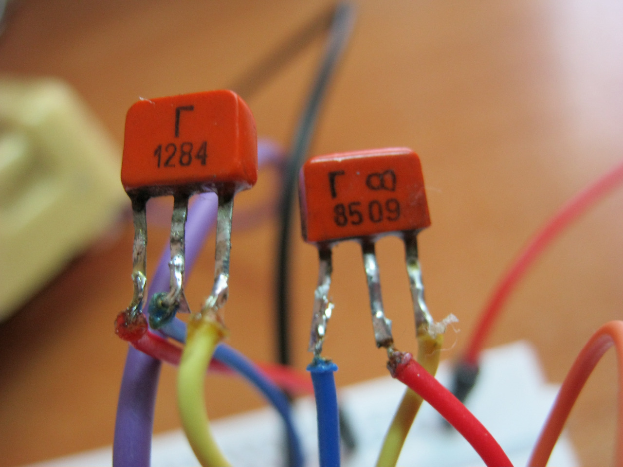
On the left is KT361G, on the right is KT315G. For KT361 the letter is located in the middle of the case, and for 315 it is on the left.
These transistors are complementary pairs to each other.
And here is the video:
The frequency of the sound can be changed by changing the value of the resistor or capacitor. Also, the frequency increases if the supply voltage is increased. At 1.5 Volts the frequency will be lower than at 5 Volts. In my video the voltage is set to 5 Volts.
Do you know what else is funny? Girls have a much greater range of perception of sound waves than boys. For example, guys can hear up to 20 Kilohertz, and girls can even hear up to 22 Kilohertz. This sound is so squeaky that it really gets on your nerves. What do I want to say by this?)) Yes, yes, why don’t we choose resistor or capacitor values such that girls hear this sound, but boys don’t? Just imagine, you are sitting in class, turning on your organ and looking at the dissatisfied faces of your classmates. In order to set up the device, we will of course need a girl to help us hear this sound. Not all girls also perceive this high-frequency sound. But the really funny thing is that it’s impossible to find out where the sound is coming from))). Only if anything, I didn’t tell you that).
http://flowmetrika.narod.ru/_pribori_docs/
SOUND FREQUENCY GENERATOR GZ-2 (ZG-10)
Rice. 1. Generator GZ-2.
The sound frequency generator GZ-2 (Fig. 1) is intended for use as a source of sinusoidal electrical oscillations of sound (low) frequency.
The device is designed for use in laboratory conditions and repair shops.
MAIN TECHNICAL CHARACTERISTICS
Range of generated frequencies from 20 to 20,000 Hz divided into three subranges: 20-200; 200-2000 and 2000-20,000 Hz.
Frequency setting error ±2%± 1 Hz.
Frequency drift after 30 min preheating for the first hour of operation no more than ±0.4%; over the next seven hours of operation, additional frequency drift is no more than ±0.4%.
Normal output power 0.5 Tue.
Maximum output power 5 Tue.
Maximum output voltage at matched load 150 V.
The output voltage changes smoothly, as well as in steps after 1 db from 0 to 110 db using two divisors: the first - after 10 db from 0 to 100 db, second - after 1 db from 0 to 10 db.
The output impedance of the generator is designed for matched loads of 50; 200; 600 and 5000 ohm
Harmonic distortion factor:
10. Uneven frequency response relative to readings at frequency 400 Hz:
at maximum output power and at all loads at frequencies from 50 to 10,000 Hz no more than ±1 db, at frequencies from 20 to 20,000 Hz no more than ±3.5 db;
at normal output power at matched load 600 ohm at frequencies from 50 to 10,000 Hz no more than ±0.5 db, at frequencies from 20 to 20,000 Hz no more than ±1.5 db.
Calibration error of the indicator scale at a frequency of 1000 Hz at voltage up to 60 V does not exceed ±5%.
Power supply of the device from an alternating current network with a frequency of 50 Hz, software voltage; 127 or 220 s±10%.
Power consumption from the network is no more than 150 va.
Dimensions: 598x357x293 mm.
Device weight no more than 35 kg.
DESCRIPTION OF THE CIRCUIT DIAGRAM
The GZ-2 generator (Fig. 2) consists of the following main elements: a master oscillator, an amplifier, an output voltage indicator, an output device and a power source.
The master oscillator is assembled using a rheostatic-capacitive circuit using lamps L 1 (6Zh8) and L 2 (6P9). An abrupt change in the frequency of the generator is carried out by switching resistances R 1 -R 11 , and smooth - by changing the capacity WITH 1 . To increase the stability of the generator, negative feedback is introduced into its circuit, in the circuit of which a thermistor TP6/2 is connected.
The bass reflex stage of the audio amplifier is made according to an auto-balanced symmetrical circuit on a lamp L 3 (6Н8С). Power amplifier with two tubes L 4 And L 5 (6С4С) operates on a push-pull circuit. The gain of the audio amplifier is about 4.
The output indicator is a diode voltmeter assembled using a full-wave circuit on a lamp L 8 (6Х6С). An M5 magnetoelectric device of class 2.5 IP 1 with a scale of 60 was used as an indicator. V, calibrated in effective voltage values at a load of 600 ohm The output device consists of two attenuators - bridge-type voltage dividers U 1 per 100 db in steps of 10 db And U 2 on 10 db in steps of 1 db and transformer Tr 3 , serving to match the generator output with loads of 50; 200; 600 and 5000 ohm A full-wave rectifier on a lamp is used as a power source L 7 (5TsZS) with a two-section L-shaped filter.
All generator tubes (except for the amplifier output stage tubes) can be replaced with ones of the same type without adjusting the generator. When changing lamps L 4 And L 5 (6C4C) it is necessary to select them so that the background level at the generator output does not exceed 15 mv. When measuring background at frequencies from 4000 to 10,000 Hz handle Reg. exit egR 22 should be set to the extreme left position, the handle Exit resistance B 2 - to position 600, switch Internal load B 4 - to position On
OPERATING THE DEVICE
Set the fuse to the position corresponding to the mains voltage.
Connect the power cable plug to an alternating current network with a frequency of 50 Hz, turn on the network toggle switch, after which the signal light should light up.
The exact frequency setting is made after a 30-minute warm-up.
Frequency setting
Frequencies of the first subband 20-200 Hz Factor is in position ×1. The frequency in hertz corresponds to the scale reading.
Frequencies of the second subband 200-2000 Hz are set by turning the scale, while the switch Factor is in position ×10, the scale reading is multiplied by 10.
Frequencies of the third subband 2000-20,000 Hz are set by turning the scale, while the switch Factor is in position ×100, the scale reading is multiplied by 100.
Setting amplitude, output voltage
1. The amplitude of the output voltage is adjusted smoothly by the handle Reg. exit eg and steps through 1 db from 0 to 110 db- handles Attenuation db.
The pointer device directly measures the output voltage at a load of 600 ohm and output attenuators (switch Exit resistance at position 600 ohm).
When the generator operates at a load of 50; 200 and 5000 ohm switch Exit resistance must be placed in a position corresponding to the load value, the readings of the dial gauge are multiplied by 0.289; 0.576 and 2.89 respectively. In this case, the toggle switch is in position Off If the load differs from the above, then it is impossible to count on the device scale.
When operating a generator on a device with a high input resistance, it is necessary to turn on the toggle switch and the switch Exit resistance put in any of four positions depending on the required voltage. In this case, the indicator scale readings are multiplied by the corresponding coefficients.

In light of the upcoming anniversary, for the competition " Congratulate Radio-Hobby with Morse code", we offer you two simple generators for learning and working on a telegraph key.
Simple low frequency generator
The circuit of a simple audio frequency (LF) generator is shown in Fig. 1. The generator circuit is assembled using transistors of different conductivities, which simplifies the circuit.

The low-frequency generator is operational with a supply voltage from 2 to 12 volts, and the desired frequency and tone are selected using resistor R1 and capacitor C1.
The range of applications of the device is varied, i.e. The low-frequency generator according to the proposed scheme can be used in various alarm systems, as well as as a sound generator for learning Morse code, etc.
radiolub.ru/page/prostoj-generator-nch
Simple generator
Quite a few audio frequency generators for studying the telegraph alphabet have been developed and described on the pages of Radio magazine. Still, the proposed generator (see diagram) will be of some interest.
Firstly, it does not have a frequency-setting capacitor. Secondly, it begins to work at a supply voltage of several tenths of a volt, even when using a transistor with a minimum transmission ratio (but not less than 10).
Generation occurs when the telegraph key SB1 is pressed due to the action of strong positive feedback between the collector and base circuits of the transistor. The sound is heard from the headphone BF1, connected to the secondary winding of the transformer. Resistor R1 sets the desired sound volume and tone.
The transistor can be any low-power silicon n-p-n structure. A p-n-p structure transistor will also work, but you will have to change the polarity of the connection of element G1. Transformer - output from any small-sized transistor receiver (for example, "Selga", "Sokol", "Almaz". "Yunost KP101". Headphone - miniature TM-2A or another similar one with a resistance of 60..300 Ohms. A DEM-4M capsule is also suitable , DEMSH, TK-67.
E. SAVITSKY, Korosten, Zhitomir region Radio, 1988, No. 3
Audio frequency generator description of the circuit operation |

Audio frequency generator circuit using transistors
Two transistors - field-effect VT1 and bipolar VT2 - are connected according to a compound repeater circuit, which has a small gain and repeats the phase of the input signal at the output. Deep negative feedback (NFE) through resistors R7, R8 stabilizes both the gain and the mode of the transistors.
But for generation to occur, positive feedback from the amplifier output to its input is also needed. It is carried out through the so-called Wien bridge - a chain of resistors and capacitors R1...R4, C1...C6. The Wien bridge weakens both low (due to the increasing capacitance of capacitors C4...C6) and high (due to the shunting effect of capacitors C1...S3). At the central setting frequency, approximately equal to 1/271RC, its transmission coefficient is maximum, and the phase shift is zero. It is at this frequency that generation occurs.
By changing the resistance of the resistors and the capacitance of the bridge capacitors, the generation frequency can be changed within a wide range. For ease of use, a tenfold range of frequency changes has been selected using dual variable resistors R2, R4, and the frequency ranges are switched (Sla, Sib) by capacitors C1...C6.
To cover all sound frequencies from 25 Hz to 25 kHz Three ranges are enough, but if desired, you can add a fourth, up to 250 kHz (this is what the author did). By choosing slightly larger capacitors or resistor values, you can shift the frequency range down, making it, for example, from 20 Hz to 200 kHz.
The next important point in designing a sound generator is stabilizing the amplitude of the output voltage. For simplicity, the most ancient and reliable method of stabilization is used here - using an incandescent lamp. The fact is that the resistance of the lamp filament increases almost 10 times when the temperature changes from a cold state to full heat! A small-sized indicator lamp VL1 with a cold resistance of about 100 Ohms is included in the OOS circuit. It shunts resistor R6, while the OOS is small, the POS predominates and generation occurs. As the oscillation amplitude increases, the lamp filament heats up, its resistance increases, and the OOS increases, compensating for the POS and thereby limiting the increase in amplitude.
A step divider is switched on at the generator output voltage on resistors R10...R15, allowing you to obtain a calibrated signal with an amplitude from 1 mV to 1 V. The divider resistors are soldered directly to the pins of a standard five-pin connector from audio equipment. The generator receives power from any source (rectifier, battery, battery), often from the same one that powers the device under test. The supply voltage on the generator transistors is stabilized by the R11, VD1 chain. It makes sense to replace resistor R11 with the same incandescent lamp as VL1 (telephone indicator, in a “pencil” version) - this will expand the limits of possible supply voltages. Current consumption - no more 15...20 mA.
Parts of almost any type can be used in the generator, but special attention should be paid to the quality of the dual variable resistor R2, R4. The author used a fairly large precision resistor from some outdated equipment, but dual resistors from volume or tone controls on stereo amplifiers will also work. Zener diode VD1 - any low-power one, for stabilization voltage 6.8...9 V.
When setting up, you need to pay attention to the smoothness of generation at approximately the middle position of the trimmer resistor R8 slider. If its resistance is too low, generation may stop in some positions of the frequency setting knob, and if its resistance is too high, distortion of the sinusoidal signal shape may be observed - limitation. You should also measure the voltage at the collector of transistor VT2; it should be equal to approximately half the voltage of the stabilized supply. If necessary, select resistor R6 and, as a last resort, the type and type of transistor YT1. In some cases, it helps to connect in series with an incandescent lamp VL1 an electrolytic capacitor with a capacity of at least 100 µF(“plus” to the source of the transistor). Finally, resistor R10 sets the signal amplitude at the output 1 V and calibrate the frequency scale using a digital frequency meter. It is common for all ranges.
The peculiarity of this sound generator circuit is that everything is built on an ATtiny861 microcontroller and an SD memory card. The Tiny861 microcontroller consists of two PWM generators and, thanks to this, is capable of generating high-quality sound, and is also capable of controlling the generator with external signals. This audio frequency generator can be used to test the sound of high-quality speakers or in simple amateur radio projects such as an electronic bell.
Audio frequency generator circuit on a timer |
The audio frequency generator is built on the popular KP1006VI1 timer microcircuit (almost according to a standard scheme. The output signal frequency is about 1000 Hz. It can be adjusted over a wide range by adjusting the ratings of radio components C2 and R2. The output frequency in this design is calculated by the formula:
F = 1.44/(R 1 +2×R 2)×C 2
The output of the microcircuit is not capable of providing high power, so a power amplifier is made using a field-effect transistor.

Audio frequency generator on a microcircuit and field switch
Oxide capacitor C1 is designed to smooth out power supply ripples. The SZ capacitance connected to the fifth output of the timer is used to protect the control voltage output from interference.
Any stabilized one with an output voltage from 9 to 15 volts and a current of 10 A will do.
Good afternoon, dear radio amateurs! Welcome to the website ““
We assemble a signal generator - a function generator. Part 1.
In this lesson Schools for beginner radio amateurs We will continue to fill our radio laboratory with the necessary measuring instruments. Today we will start collecting function generator. This device is necessary in the practice of a radio amateur to set up various amateur radio circuits– amplifiers, digital devices, various filters and many other devices. For example, after we assemble this generator, we will take a short break during which we will make a simple light-music device. So, in order to correctly configure the frequency filters of the circuit, this device will be very useful to us.
Why is this device called a functional generator, and not just a generator (low frequency generator, high frequency generator). The device that we will manufacture generates three different signals at its outputs: sinusoidal, rectangular and sawtooth. As a basis for the design, we will take S. Andreev’s diagram, which is published on the website in the section: Circuits – Generators.
First, we need to carefully study the circuit, understand the principle of its operation and collect the necessary parts. Thanks to the use of a specialized microcircuit in the circuit ICL8038 which is precisely intended for building a function generator, the design turns out to be quite simple.


Of course, the price of the product depends on the manufacturer, and on the capabilities of the store, and on many other factors, but in this case we are pursuing one goal: to find the necessary radio component that would be of acceptable quality and, most importantly, affordable. You probably noticed that the price of a microcircuit greatly depends on its marking (AC, BC and SS). The cheaper the chip, the worse its performance. I would recommend choosing the “BC” chip. Its characteristics are not very different from “AS”, but much better than those of “SS”. But in principle, of course, this microcircuit will also work.
We assemble a simple function generator for the laboratory of a novice radio amateur
Good day to you, dear radio amateurs! Today we will continue to collect our function generator. So that you don’t jump around the pages of the site, I’ll post it again functional generator circuit diagram, which we are assembling:

I’m also posting a datasheet (technical description) of the ICL8038 and KR140UD806 microcircuits:
(151.5 KiB, 6,062 hits)
(130.7 KiB, 3,494 hits)
I have already collected the necessary parts to assemble the generator (I had some - constant resistances and polar capacitors, the rest were purchased at a radio parts store):

The most expensive parts were the ICL8038 microcircuit - 145 rubles and switches for 5 and 3 positions - 150 rubles. In total, you will have to spend about 500 rubles on this scheme. As you can see in the photo, the switch with five positions is two-section (there was no one-section), but this is not scary, more is better than less, especially since we may need the second section. By the way, these switches are absolutely identical, and the number of positions is determined by a special stopper, which you can set to the required number of positions yourself. In the photo I have two output connectors, although in theory there should be three: common, 1:1 and 1:10. But you can install a small switch (one output, two inputs) and switch the desired output to one connector. In addition, I want to draw attention to the constant resistor R6. There is no rating of 7.72 MOhm in the line of megaohm resistances; the closest rating is 7.5 MOhm. In order to get the desired value, you will have to use a second 220 kOhm resistor, connecting them in series.
I would also like to draw your attention to the fact that we will not finish assembling and adjusting this circuit to assemble a function generator. To work comfortably with the generator, we must know what frequency is being generated at the moment of operation, or we may need to set a certain frequency. In order not to use additional devices for these purposes, we will equip our generator with a simple frequency meter.
In the second part of the lesson, we will study another method of manufacturing printed circuit boards - the LUT (laser-iron) method. We will create the board itself in a popular amateur radio program for creating printed circuit boards – SPRINT LAYOUT.
I won’t explain to you how to work with this program yet. In the next lesson, in a video file, I will show you how to create our printed circuit board in this program, as well as the entire process of making a board using the LUT method.