Schematic diagram of a voltage converter 12-220V. High voltage and more. Inverter fault detection
I propose a 12/220V voltage converter (inverter) circuit (power up to 500 Watt), powered by a 12V battery, which can be useful in a car and at home for lighting, for powering a TV, a small refrigerator, etc. The circuit is assembled on two 155 series microcircuits and six transistors. The output stage uses field-effect transistors that have a very low on-state resistance, which increases the efficiency of the converter and eliminates the need to install them on radiators that are too large.

Let's figure out how the circuit works: (see diagram and diagram). The D1 chip contains a rectangular pulse generator, the repetition rate of which is about 200 Hz - diagram “A”. From pin 8 of the microcircuit, pulses are sent further to frequency dividers assembled on elements D2.1 - D2.2 of microcircuit D2. As a result, at pin 6 of the D2 chip, the pulse repetition rate becomes half as much - 100 Hz - diagram "B", and at pin 8 the pulses become equal to the frequency of 50 Hz - diagram "C". Non-invertible 50 Hz pulses are removed from pin 9 - diagram “D”. An “OR” logic circuit is assembled on diodes VD1-VD2. As a result, the pulses taken from the pins of microcircuits D1 pin 8, D2 pin 6 form a pulse corresponding to diagram “E” at the cathodes of the diodes. The cascade on transistors V1 and V2 serves to increase the amplitude of the pulses necessary to fully open the field-effect transistors. Transistors V3 and V4 connected to outputs 8 and 9 of microcircuit D2 open alternately, thereby locking either one field-effect transistor V5 or another V6. As a result, control pulses are formed in such a way that there is a pause between them, which eliminates the possibility of through current flowing through the output transistors and significantly increases efficiency. Diagrams "F" and "G" show the generated control pulses for transistors V5 and V6.
A correctly assembled converter begins to work immediately after power is applied. When setting up, you should connect a frequency meter to the output of the device and set the frequency to 50-60 Hz by selecting resistor R1, and, if necessary, capacitor C1.
About details
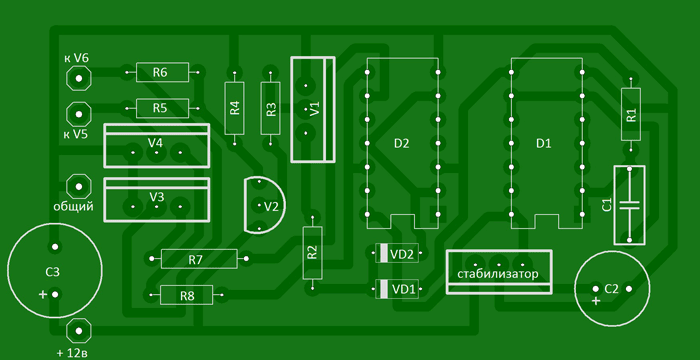
Transistors KT315 with any letter index, KT209 can be replaced with KT361 with any letter index. We will replace the KA7805 voltage stabilizer with the domestic KR142EN5A. Any resistors with a power of 0.125...0.25 W. Almost any low-frequency diodes, for example KD105, IN4002. Capacitor C1 type K73-11, K10-17V with low capacity loss when warming up. The transformer was taken from an old tube black and white TV, for example: “Spring”, “Record”. The 220 volt winding remains, and the remaining windings are removed. Two windings are wound on top of this winding with PEL wire - 2.1 mm. For better symmetry, they should be wound simultaneously into two wires. When connecting the windings, take into account the phasing. Field-effect transistors are fixed through mica spacers to a common aluminum radiator with a surface area of at least 600 sq.cm.

List of radioelements
| Designation | Type | Denomination | Quantity | Note | Shop | My notepad |
|---|---|---|---|---|---|---|
| Linear regulator | UA7805 | 1 | KR142EN5A | To notepad | ||
| D1 | Valve | K155LA3 | 1 | To notepad | ||
| D2 | D-trigger | K155TM2 | 1 | To notepad | ||
| V1, V3, V4 | Bipolar transistor | KT315B | 3 | To notepad | ||
| V2 | Bipolar transistor | KT209A | 1 | KT361 | To notepad | |
| V5, V6 | MOSFET transistor | IRLR2905 | 2 | Through mica spacers | To notepad | |
| VD1, VD2 | Diode | KD522A | 2 | KD105, 1N4002, etc. | To notepad | |
| C1 | Capacitor | 2.2 µF | 1 | K73-11, K10-17V | To notepad | |
| C2 | 470 µF | 1 | To notepad | |||
| C3 | Electrolytic capacitor | 2200 µF | 1 | To notepad | ||
| R1 | Resistor | 680 Ohm | 1 | To notepad | ||
| R2 | Resistor | 7.5 kOhm | 1 | To notepad | ||
| R3, R5-R8 | Resistor |
There are completely different situations when the owner needs to create a new voltage converter at home. The main purpose of this device is to provide a mains voltage value of 220 V from the original values of 12 W. The 12 to 220 inverter is made by hand by most amateurs, since a good quality inverter is quite expensive. Before assembling the device, you should understand the principle of its operation in order to have an idea of the mechanism of its operation.
In what areas is a 12-220 V voltage inverter used?
With stable use of the battery, its charge level gradually decreases. The converter stabilizes the voltage if there is no electricity.
A 12-220 V inverter made by yourself will allow you to improve engineering structures in any room. The power value of devices that convert current is selected according to the total values of the loads being used. Power consumption processes can be reactive or active. Reactive loads do not fully consume the amount of energy received, causing the apparent power value to be greater than its active value.
![]()
Pure sine wave inverters are used when connecting an element whose total power is 3 kW.
Significant fuel savings are ensured by the use of voltage converters and mini-power plants.
- The following consumers are connected to the inverter design:
- alarm system;
- boiler;
- pumping apparatus;
computer system.
Advantage of using voltage converters

Due to the fact that inverters have a number of positive characteristics, they are highly valued when used for various types of electrical equipment. The devices operate silently and do not pollute the environment with all kinds of emissions. The cost of servicing such devices is minimal: there is no need to check the pressure in the engine. Inverters have fairly insignificant mechanical wear, which allows them to be used by various consumers. Inverters 12-220 V operate at increased powers KR121 EU and have increased efficiency.
In the process of assembling inverters with master devices as multivibrators, the advantage of the converters is that the device is accessible and simple. The size of the products is compact, repairing them is not difficult, and they can be operated even at low temperatures.
Scheme and principle of operation of the inverter 12 220
The main part of radio components that use inverters use high frequencies in their operation. A pulse inverter completely replaces the classical circuit that uses transformers. The K561TM2 microcircuit is formed by two D-triggers, which have an R and S input. Such a microcircuit is created taking into account the use of CMOS technologies, by enclosing it in a plastic case.

The inverter master generators are mounted taking into account the K561TM2, using the DD1 device for operation. The DD1.2 trigger is mounted on the frequency divider. The amplification stages receive the signal from the microcircuits.
For operation, KT827 transistors are selected. If they are missing, then a transistor like KT819 GM or a field-effect semiconductor - IRFZ44 will do.
Generators with a sine wave for a 12-220 V inverter operate at high frequencies. To form a circuit with a size of 50 Hz, use a secondary winding with a parallel connection of capacitors and loads. By connecting any device, inverters create a conversion voltage of 220 V.
Speaking about how the 12 220 inverter works, it is worth pointing out that the K561TM2 chip is duplicated by the K564TM2. You can increase the power on the converter by selecting a more intense transistor. It is important to take into account the fact which capacitors are installed at the outputs. They have a voltage of 250 V.
Converter with the latest parts
A homemade inverter can operate in a stable mode if the transistor at the outputs operates from an amplified source with the main generator. For this purpose, it is allowed to use elements of the KT819GM series installed on dimensional radiators.
When creating converters, a simplified scheme is used. As the process progresses, you should take care of purchasing the necessary materials:
- KR121EU1 microcircuits;
- transistors IRL2505;
- soldering iron;
- tin.
KR12116U1 microcircuits have a remarkable property: they contain a pair of channels for regulating the switch and allow you to quite simply make a simple voltage converter. Microcircuits in the temperature range from +25 to +30°C produce a maximum voltage value within the range of 3 and 9 V.

The frequency of the master oscillators is determined by the parameter of the element in the circuits. The IRL2505 transistor is installed when used on the outputs. It must receive a signal with the proper level, due to which the output transistor is adjusted.
The formed low levels do not allow the transistor to transition from closed modes to any other states. As a result, the occurrence of instantaneous current flows during simultaneous opening of the keys is completely eliminated. If high levels are observed to reach the first output, then this helps to turn off pulse generation. The circuit determines the connection of the common wire to pin 1.

To install push-pull cascades, T1 transformers and two transistors are used: VT1 and VT2. In open channels you can see a resistance value of 0.008 Ohm. It is insignificant, and therefore the power value of the transistor is small, even if a large current passes. Output transformers with a power of 100 W allow the IRL2505 to apply a current of 104 A, and pulse transformers are 360 A.
The main features of inverters include the ability to use any transformer that has two 12 V windings at its outputs.
If the output power is about 200 W, then in such cases the transistor is not installed on the radiator. It is important to consider that the value of electric current with a power of 400 W reaches about 40 A.
How does an inverter for fluorescent lamps work?
To make a converter that will illuminate a room of any size or car, it is enough to use a DIY assembly diagram. VOLTSL pulse converters are push-pull. They are mounted on power supplies TL 494 (KS 1114EU4). The microcircuits are controlled by the power parts of the power supply and consist of:
- voltage generator;
- voltage stabilizing source;
- two transistors on the output sources of electric current, the capacity of which is 0.7 mm and 0.1 V.
To complete the installation, it is necessary to provide for the purchase of rectifier diodes and a transformer from the power supply. The issue of rewinding transformers should be addressed. When performing this work yourself, you should calculate up to 100 kHz. Each resistor is purchased, taking into account the circuit R1 and R2, creating the passage of a current pulse at the output. The operating frequency is formed when creating the circuit C1 and R3. HR307 diodes are mounted, but if they are not available, then use HER304. KD213 diodes have proven themselves quite well. The selection of capacitors is carried out with different capacities. Soldered chips are placed in panels. The circuits can operate for four hours - the design of the transistors does not overheat, and they do not need tuning.
Transformers are subject to independent winding. Therefore, it is necessary to stock up on ferrite rings with a diameter of 30 mm in advance. The basis uses a winding turns ratio of 1:120, while 1:1 is the primary winding and 20 is 200 turns with a secondary winding.
Initially, the secondary winding is wound using a wire with a cross-section of 0.4 mm. At the next stage, a primary coating is created, which consists of 2 halves of ten turns on each of them. Stranded soft wire with a diameter of 0.8 mm is used to create a half-winding. To remake the transformer, it is possible to use a device for a 12-volt lamp that illuminates the ceiling. The secondary winding is removed, and the half-winding is created by winding the coverings when the wire is folded in half. After this, the connecting point is cut, and each end of the wires is soldered together, thereby forming the center of the winding.
For uninterrupted operation, it is necessary to use powerful metal conductors or field-effect transistors IRFL44N LRF46N. For converters, diodes HER307 and KD213 are installed. Computer power supplies with a diameter of 18 mm are used as capacitors.
During prolonged operation, the transistors heat up and radiators are not installed. If it is intended to be used, then the flanges on the transistor housing should not be wrapped through resistors. You should use a washer and spacer insulating materials from PC power supplies.
Inverters are reliably protected from overload if a fuse and diode are installed at the outputs. It is important that safety regulations are strictly followed: that is, high voltages must be avoided. Charges in capacitors can be stored for 24 hours. Discharge is carried out using 220 V incandescent lamps.
A 12V 220 inverter with your own hands can be made according to a simple diagram. Such a device is considered a fairly convenient device that allows you to receive a voltage of 220 V. Any devices made at home, in some situations, are absolutely in no way inferior to factory-made products, and in some cases even surpass them.
Video “Creating a converter for fluorescent lamps”
Everyone is accustomed to electrical appliances operating on 220V. But what if you go on a hike or some long trip, and want to take convenient household appliances with you? They will not be able to work directly from the car battery; they simply do not have enough power. This is where voltage converters from 12 to 220V can come to the rescue.
What is a converter and its essence
Thanks to technological progress, these devices have become an order of magnitude smaller and more convenient. They are easy to carry and do not take up much space. The converters are capable of raising the battery voltage to 220V. They even work from the cigarette lighter. With the help of such inverters, you can easily install lighting in a tent, as well as power your tablet, laptop, and phone from them.

PWM controllers have made such devices more advanced. The efficiency increased noticeably, and the current shape became similar to a pure sine wave. But this is only in expensive devices. It became possible to increase power to several kW.

The duration of operation depends on the power and capacity of the batteries. Therefore, when going on a trip, it is better to limit yourself to electrical appliances with low energy consumption.


Today it is possible to buy various types of current converters that can produce power from several hundred watts to several kW. But for tourist trips it is worth purchasing a low-power inverter.

The only obstacle to their full application is the altered current shape. From an ordinary sinusoid, it turns into an almost rectangular shape. Not all household appliances are capable of working on it.

There are 3 types of converter design:
- Automotive;
- Compact;
- Stationary.

It is worth noting that by increasing the load, the efficiency of the converter decreases. Stationary inverters can produce a sine wave. They are convenient to use to increase voltage from wind generators and solar panels.

Converter characteristics
Before purchasing, you need to know how to choose a voltage converter. The first thing you should pay attention to is its characteristics. Often sellers give incorrect inverter performance. Indicate its peak power, at which the device can operate for several minutes, after which it turns off due to overheating. This is how the most affordable converters are advertised.

Powerful DC-AC converters increase the voltage from 12V to 220V, the current shape and frequency are equal to the usual indicators of a home network. Therefore, all devices and tools are capable of working from it.

All current converters have the following parameters:
- Operating power;
- Cooling type;
- Energy consumption during idle operation;
- Maximum input current consumption;
- Protective mechanisms against short circuit and overheating;
- Output current shape;
- Voltage level for power supply.

The high efficiency of modern inverters is due to the pulse controllers used in the design. Almost 95% of the energy goes to the payload. The rest dissipates in the device and heats it.


In the simplest and most accessible converters, the current sinusoid changes. It becomes rectangular, and in expensive and powerful devices the current shape remains the same smooth sinusoid as in a standard outlet.

Sometimes, the power of voltage converters may not be enough to run construction tools. For example, if a drill consumes 750W, then it will not run on a 1000W inverter. To solve this problem, soft starters are sold.

Stationary type converters are used for home work. These are powerful devices capable of delivering several thousand watts. More serious converters are used in enterprises; their power amounts to tens of thousands of watts.

For cars, low-power inverters of several hundred watts are used. Because the battery is not capable of operating for a long time under heavy loads.


It is not recommended to use the converter at maximum loads. Its service life will quickly decrease. Expensive devices have a power reserve, and in the most affordable ones this figure is slightly less than what is indicated on the case.

You need to buy a device that is 20% more powerful than the expected consumption. You also need to be interested in the type of power indicated on the case. She may be:
- nominal;
- long-lasting;
- short-term.

Cooling type
Aluminum is a metal with high thermal conductivity, and converters (especially powerful ones) can overheat when operating under heavy loads. Therefore, the cases are made from this metal.

For an active cooling system, a fan is mounted in the case. It turns on when the temperature sensor detects an increase in temperature. In car inverters, fans can become clogged with dust, which leads to poor air ventilation and overheating.

The case may have passive cooling elements. They look like aluminum fins that help dissipate heat.


Homemade converter
Radio amateurs have the opportunity to make a simple inverter using the circuit. The result is a compact device capable of powering various pocket gadgets.


There are only four transistors in the circuit. Anyone who knows how to use a soldering iron can assemble it. The resulting device is convenient to use in a car. It is capable of providing a full-fledged 220V on-board socket.

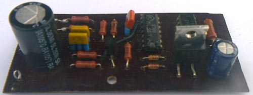
Photos of converters from 12 to 220


A 12 volt to 220 volt converter with a maximum output power of 500 W is assembled on 2 domestic microcircuits (K155LA3 and K155TM2) and 6 transistors, and several radio components. To increase efficiency and prevent strong heating, very powerful IRLR2905 field-effect transistors with minimal resistance are used in the output stage of the device. It is possible to replace it with IRF2804, but the power of the converter will drop slightly
Using elements DD1.1 - DD1.3, C1, R1, a master generator of rectangular pulses with an approximate frequency of 200 Hz is assembled according to the standard circuit. From the output of the generator, pulses follow to a frequency divider consisting of elements DD2.1 - DD2.2. As a result, at the output of the divider (pin 6 of element DD2.1), the pulse repetition rate is reduced to 100 hertz, and at output 8 of DD2.2. The signal frequency is 50 hertz.
The rectangular signal from pin 8 of the DD1 chip and from pin 6 of the DD2 chip is supplied to the diodes VD1 and VD2, respectively. In order for the field-effect transistors to open completely, it is necessary to increase the amplitude of the signal that comes from the diode VD1 and VD2; for this, transistors VT1 and VT2 are used. With the help of transistors VT3 and VT4 (they act as a driver), the output power transistors are controlled. If no errors were made during the assembly of the inverter, then it starts working immediately after switching on. It is possible that it may be necessary to select the resistance of resistor R1 so that the output is exactly 50 hertz.
Voltage converter (inverter) 12 / 220 50 Hz 500 W DIY circuit
Silicon transistors VT1, VT3 and VT4 - KT315 with any letter. Transistor VT2 can be replaced with KT361. Stabilizer DA1 is a domestic analogue of KR142EN5A. All resistors in the circuit have a power of 0.25 W. Any diodes KD105, 1N4002. Capacitor C1 with a stable capacitance - type K10-17. As a transformer TP1, it is possible to use a power transformer from an old Soviet TV. All windings must be removed, leaving only the network winding. On top of the network winding, wind two windings simultaneously with PEL wire - 2.2 mm. Field-effect power transistors must be installed on an aluminum finned radiator with a total area of 750 sq.cm.It is recommended that the converter (inverter) be started for the first time through a household incandescent lamp of 220 volts and a power of 100 - 150 watts, connected in series to one of the supply wires, this will protect you from damage to radio components in the event of an error.
When working with boost converters or inverters, follow the electrical safety rules since the work is carried out with a voltage dangerous to the body!!! During the commissioning and assembly process, the output secondary winding must be insulated with rubber tube cambrics to avoid accidental contact.