Turbodflower for ventilation: principle of operation and comparison of types of rotary deflectors. Wind turbines are the wind generators of the third generation The main types of windmills
Excessive humidity and odors create an unhealthy atmosphere and even become causes of diseases. The quality of ventilation in the house, office or production directly affects the level of comfort, do you agree with that?
That is why competently arranged ventilation is the most important condition When commissioning construction objects. To establish a high-quality air exchange helps the turbo flower for ventilation. But what to choose and correctly install so as not to call specialists?
We will try to answer in a detailed answer to all the questions - in this material it is considered the principle of operation, existing varieties of turbo brekers, the features of the installation. And also paid attention to service and repair issues.
For a better understanding of the outlined information, visual photos and schemes of the device of rotary deflectors are selected, video recording video recording is given. Information is structured and even inexperienced homemade craftsman will be easy to deal with the intricacies of the choice, installation and repair of the rotational deflector.
The work of the turboFloflector is based on the following principles: Using wind energy, the device creates air cutting in the ventilation mine, increases the thrust and pulls the contaminated air out of the room, the ventilation channel, the underpants.
No matter how the direction and the strength of the wind, the rotating head (impeller) is always spinning in one direction and creates a partial vacuum in the ventilation mine.
Gallery of images
Turbine mounting rules
Ventilation turbines can be installed directly onto the pitched or direct roof, on the departure of the chimney or ventilation mines. The placement site depends on the scope of the turbine.
The influx of clean air into the room provides ventilation system. Its effectiveness depends on the inner traction. If you get into the dust and garbage duct channels, the normal operation of devices is broken. To eliminate such a likelihood at the outlet of the pipe set the fan deflector - the device that shakes the thrust in Ventscanlas . Why do you need such an aggregate? - This device can protect the air duct mines from moisture, snow and rain.
note! The absence of this solution leads to a gradual decrease in the pipe diameter due to the fact that small particles of garbage, dust and fat accumulate on the walls of the pipes.
On sale presented a wide range of models. Their device and the principle of operation are discussed below. The simplest models can be made with your own hands.
- metal glasses (in the standard version 2);
- fixing brackets for reliable fastening;
- supply-removing nozzle, which is put on the pipe and is attached using a clamp.
- the directional streams of the wind hit the metal case;
- due to the diffusers, the air branches itself, as a result of which the pressure level decreases;
- in the pipe system rises.
- construction and shape of the housing;
- aggregate size;
- installation height.
- TsAGA - thrust increases due to air and thermal pressure, a high pressure drop. Mounted directly into the ventilation channel, which makes it difficult for preventive inspections and cleaning;
- round or round (type "Volper");
- solutions Hangzkova in the form of a plate open type - The main design difference lies in an additional wall located around the duct. The exhaust umbrella has a plate shape;
- rotary products (hood, sump) - a gutter for wind, which rotates on a special stock. Due to the turbulence of thrust in the channel increases;
- aggregates operating on the principle described by Grigorovich;
- in the form of a star.
- Astato;
- TsAGA type.
- stainless steel sheet type, can be replaced with galvanized;
- electric drill;
- fixing clamps, bolts, rivets and nuts;
- intestinal tool for metal surfaces;
- compass;
- sheet cardboard;
- line;
- scissors for metal and paper.
- the height of the deflector is 1.6 diameter of the chimney.
- the width of the diffuser is 1.2 times more than the diameter of the chimney.
- the width of the lid is equal to two chimney diameters.
Show all
Ventilation deflector device
Each turbo flower for ventilation consists of several functional elements:
In the form, the outer glass is characterized by a form expanding at the bottom. As for the lower, it is absolutely even. The cylinders are put on one on the other, and the top of the racks are fixed at the top.
Attention! The diameter of the lid should be larger outlet to avoid falling in the system inside the system.
Figure below shows the composite parts different types constructions.
note! Installation of sebeth is carried out in such a way that the street air creates an additional sucks through the recesses between adjacent rings. Due to this, you can speed up the removal of "heavy oxygen" from ventilation system .
The deflector devices in the ventilation system of the house are realized in such a way that when the air flow direction is from the bottom to the top, the device works badly: it is reflected from the roof surface, after which the oxygen rushes to gases leaving at the top of the opening. This deficiency is typical for all aggregates. To eliminate it requires 2 cone solutions, connections to each other "bridge".
If the wind has a lateral direction, the withdrawal of the air masses is carried out both from below and from above. The vertical direction of oxygen contributes to the outflow from the bottom.
What is turboodefliktor? Ventilation without electricity. Replacing the usual ventilation system


Principle of action of the ventilation deflector
The ventilation deflector works on simple principle, regardless of the design and model of the device:
Principle of operation of the device
The greater the resistance creates the base of the housing, the more efficient the air outflow in the channels of systems. It is believed that the device installed on a low inclination to the horizontal plane works better than the roof. Specialists state - the effectiveness of these devices is determined by 3 factors:
No matter how reliable and high-quality ventilation deflectors, they have both the advantages and disadvantages that would like to stop more.
O "pluses" and minuses of deflectors
As mentioned above, umbrella decisions are able to effectively prevent the ingress of dirt and precipitation into the air ducts. In the competent selection and professional installation of the deflector, ventilation improves. The efficiency of the system as a whole increases by 20%.
The ventilation device helps to create or increase air craving in exhaust ventilation channels.
Council! For regions with weak winds, it is recommended to equip the system by the system to enhance the inflow and air removal. It will exclude the "tipping" effect.
The devices are not deprived of the flaws: with the vertical direction of the wind, the flow comes into contact with the upper part of the structure, while the air cannot fully remove into the street. To eliminate such an effect and constructs with 2 cones were invented. IN winter On the basis of pipes appears, followed, so it is necessary to regularly carry out preventive inspections.


Types of deflectors
After analyzing or fluently looking at the types of deflectors, presented on the market, one can come to a state of lightly confusion from the amount of solutions available.
From the point of view of the design of the device, it is customary to divide into several types:
From the point of view of ease of construction and the possibility of implementation, unconditional leadership holds the Gregorovich ventilation device. It represents several pairs of umbrellas arranged in one "plate", which is mounted over the channel wall.
Grigorovich device
In the last 2-3 years, a variety of products are found on sale that have no clear accessories to any kind: a rotating deflector with spiral blades, an umbrella, aggregates on bearings.
When choosing a specific model, paramount attention is paid to its design. This is one of the key parameters of the product. Deciding with the structural type of device, selected optimal size aggregate for specific case. The desired device is easier to choose if you give an answer to a simple question - why the design is installed and for which object.
Best models:
When choosing, the coefficient of loss and air discharge is taken into account. It follows from this that these values \u200b\u200bdepend on the specific model. If we are talking about DS solutions, the corresponding coefficient will be 1.4. Obviously, the degree of air discharge depends on the wind speed, Table. below:
Table for device selection
Ventilation deflector do it yourself
Knowing the device and principle of operation of the device, many owners are solved on the manufacture of a ventilation deflector with their own hands. From the point of view of its own implementation, the version of the Grigorovich product is out of competition, so we will consider the implementation of this particular option. The main advantage is such ventilation without electricity, all year round.
Previously prepare:
Calculation of device parameters (Grigorovich)
We give you the easiest option of calculation, without any formula:
Based on the existing sizes and drawings of cardboard, individual elements of the deflector are cut. To create a rotating device, certain skills are required, so it is better to practice on layouts and only then begin a metallic analogue.
Manufacturing design
Pekal must be applied to metal sheets, and after - to circulate the devil. Next, the algorithm is simple - metal scissors cut out the elements and details of the future design. Separate parts are combined with rings and bolts. If the mechanism is active, it is better to fix the parts with welding.
Layouts Deflectors for ventilation systems from cardboard
To securely fix the rotary cap, several curved metal strips should be prepared, which will take the role of brackets.
Krepim brackets with rivets or bolts
As for the reverse cone, it makes sense to fix the umbrella.
Deflector
Mounting work
The lower from 2 glasses is installed on the output of the chimney. The top glass is attached to it. For a larger stability design of 2 parts, clamps are clamping, in the same way and with exhaust holes. The cap is pressed by the prepared brackets. If we are talking about the region where the direction of the wind is often changing, it makes sense to equip the installation by the reverse cone, which will allow the unit to fully work at any direction of wind.
So, in this article we considered that such a deflector in ventilation. Summing up, one can say is a simple and effective device that improves ventilation of objects of any complexity, whether public buildings or residential buildings. A small element increases the performance of the ventilation system by 15-20%, reliably protecting inner space From precipitation, small particles, garbage and dust.
Russia in relation to wind power resources occupies a dual situation. On the one hand, thanks to a huge total area and the abundance of the plated areas of the wind as a whole, and it is mostly smooth. On the other hand, our winds are predominantly low-precious, slow, see fig. With the third, in a few rolled areas of the winds of rains. Based on this, the task of getting a wind generator is quite relevant on the farm. But to decide - buy a fairly expensive device, or make it with your own hands, you need to think about what type (and there are a lot of them) for what purpose to choose.

Basic concepts
- Keev - the coefficient of use of wind energy. In the case of application for calculating the mechanistic model of a flat wind (see below), it is equal to the efficiency of the wind rotor (VSU).
- The efficiency is a cross-cutting efficiency of the WMS, from the incident wind to the terminals of the electric generator, or to the amount of water pumped into the water tank.
- The minimum wind operating speed (MRC) is the speed of it at which the windmill begins to give a current to the load.
- The maximum allowable wind speed (MDS) is its speed at which energy generation stops: automation or turns off the generator, or puts the rotor into the weather vane, or folds it and hides, or the rotor itself stops, or the NPU is simply destroyed.
- The starting speed of the wind (CER) - with such a speed, the rotor is able to be checked without load, promotion and log into the operator, after which the generator can be turned on.
- Negative start speed (OSS) - this means that the VSU (or VEU is wind power unit, or VEA, wind power unit) to start at any wind speed requires a mandatory promotion from an extraneous energy source.
- The starting (initial) moment is the ability of the rotor, forcibly inhibited in the air flow, create a torque on the shaft.
- A wind turbine (VD) is part of the VSU from the rotor to the shaft of the generator or pump, or another energy consumer.
- The rotary wind generator - the ASU, in which the wind energy is converted into the rotational moment on the power take-off shaft by rotating the rotor in the air flow.
- The rotor operating speed range is the difference between MDS and MRC when working on a nominal load.
- A slimmer - in it the linear velocity of the parts of the rotor in the stream does not exceed the wind speed or below it. Dynamic stream pressure is directly converted to the blade.
- Speed \u200b\u200bwindmills - the linear velocity of the blades is essential (up to 20 or more) higher wind speed, and the rotor forms its own air circulation. The flow cycle of the stream energy in the craving is complex.
Notes:
- Thexious WSUs, as a rule, have a keeve lower than the high-speed, but have a starting point, sufficient to promote the generator without turning off the load and zero CER, i.e. Absolutely self-missing and applicable for the weakest winds.
- Sourgelessness and speed - the concepts are relative. The household windmill on 300 rpm can be low, and the powerful EUROWIND VSUs, from which the fields of wind turbines are gaining, VES (see Fig.) And the rotors of which make about 10 rpm - fast, because With this diameter, the linear velocity of the blades and their aerodynamics are completely "aircraft" for most of the scope, see further.

What is the generator?
The electrical generator for domestic windmill must produce electricity in a wide range of rotational speeds and have self-wave ability without automation and external power sources. In the case of using the ASS with the OSS (windmill with promotion), possessing, as a rule, high cyser and efficiency, it must be reversible, i.e. Be able to work and like the engine. With capacities up to 5 kW, this condition is satisfied electric cars with constant niobium-based magnets (supermagnets); On steel or ferrite magnets, no more than 0.5-0.7 kW can be calculated.
Note: Asynchronous generators alternating current Or collector with a slightly adjacent stator are not suitable at all. With a decrease in the strength of the wind, they will "go out" long before its speed falls to the MRC, and then they will not be launched.
The excellent "heart" of the WME with a power of 0.3 to 1-2 kW is obtained from an AC autogenerator with a built-in rectifier; Most of these now. First, they keep the output voltage of 11.6-14.7 V in a rather wide range of speeds without external electronic stabilizers. Secondly, silicon valves open when the voltage on the winding reaches about 1.4 V, and before that the generator "does not see" the load. For this, the generator needs to be quite decently promoted.
In most cases, the autogenerator can be directly, without a toothed or belt transmission, to connect with the high-speed VD shaft, pickover with the choice of the number of blades, see below. "Battleships" have a small or zero starting point, but the rotor and without turning off the load, it will be enough to unleash enough before the valves open and the generator will give the current.
Choice by wind
Before deciding to make a wind generator, we will define local aerology. In gray-greenish (windless) windscreen areas at least some sense will be only from sailing wind turbine (And then let's talk). If constant power supply is necessary, then you will have to add booster (rectifier with voltage stabilizer), charger, powerful battery, inverter 12/24/36/48 in constant in 220/380 in 50 Hz alternating current. Such an economy will cost at least $ 20,000, and to remove the long-term power of more than 3-4 kW is unlikely to succeed. In general, with an adamant desire for alternative energy, it is better to look for another source.
In yellow-green, weakly-rich places, with the need for electricity up to 2-3 kW, you can most like a fat vertical wind generator . They are developed to bear numbers, and there are structures, by Keev and the efficiency almost not inferior to "vane" industrial manufacture.
If VEU for the house is supposed to buy, then it is better to navigate the windmill with a sailing rotor. Disputes and they are a lot, and in theory is not yet clear, but they work. In the Russian Federation "Sailboats" produced in Taganrog to the capacity of 1-100 kW.
In red, windy, regions, the choice depends on the required power. In the range of 0.5-1.5 kW, improvised "vertical"; 1.5-5 kW - purchased "sailboats". The "vertical" can also be purchased, but it will cost the HRU of the horizontal scheme. And finally, if a windmill with a capacity of 5 kW and more, then you need to choose between horizontal purchased "lobaters" or "sailboats".
Note: many manufacturers, especially the second echelon, offer parts sets from which you can collect a wind generator with a capacity of up to 10 kW. Such a set by 20-50% is cheaper than finished with installation. But before purchases you need to carefully examine the aerology of the intended place of installation, and then the specification to select the appropriate type and model.
About security
Details of domestic wind turbines in the paper may have a linear speed, superior to 120 and even 150 m / s, and a piece of any solid material weighing 20 g, flying at a speed of 100 m / s, with a "successful" hit kills a healthy man. Steel, or out of rigid plastic, a plate with a thickness of 2 mm, moving at a speed of 20 m / s, dissecting it in the same way.
In addition, most wind turbors with a capacity of more than 100 W are quite noisy. Many generate air pressure fluctuations with ultra-low (less than 16 Hz) frequency - infrasound. Infrasounds are inadvertible, but destructives for health, but spread very far.
Note: in the late 80s, the USA was a scandal - I had to close the largest VES in the country at that time. The Indians from the reservation 200 km from the field of its Armed Forces were proved in court that they had sharply frequent after entering the WCEC into operation of health disorder were due to its infrasounds.
By virtue of the above reasons, the installation of the WWU is allowed at a distance of at least 5 of their heights from the nearest residential buildings. In the courtyards of private households, industrial manufacturing windmills can be installed, correspondingly certified. On the roofs, it is impossible to put on the roofs - with their work, even at low-power, there are alternating mechanical loads that can cause resonance building construction and its destruction.
Note: the highest point of the overemost disk (for blade rotors) or a geomery figure (for vertical ASUs with a rotor on ancient is considered height. If the Mast of the VSU or the axis of the rotor protrude upwards even higher, the height is considered to be the top of them.
Wind, aerodynamics, cyser
The homemade wind generator obeys the same laws of nature as the factory, calculated on the computer. And the home owl of the foundation of his work should be understood very well - at his disposal most often there are no expensive super-modern materials and technological equipment. Aerodynamics Oh, oh, how difficult ...
Wind and Keev
To calculate the serial factory AMU, T. Naz. Flat mechanistic wind model. It is based on the following assumptions:
- The speed and direction of the wind is constant within the efficient surface of the rotor.
- Air is a solid medium.
- The effective surface of the rotor is equal to oven.
- Airflow energy - pure kinetic.
Under such conditions, the maximum energy of the air volume unit is calculated by the school formula, believing air density under normal conditions 1.29 kg * cube. m. When wind speed 10 m / s One cube of air carries 65 J, and from one square of the effective surface of the rotor, with 100% efficiency of the entire Armed Forces, remove 650 W. This is a very simplified approach - everyone knows that the wind is perfectly smooth. But it has to go to ensure the repeatability of the products - the usual thing in the technique.
Flat model should not be ignored, it gives a clear minimum of the available wind energy. But the air, firstly, compress, secondly, very tech (dynamic viscosity of only 17.2 MCP * C). This means the flow can contend the overall area, reducing the effective surface and the keeve, which is most often observed. But in principle, the reverse situation is possible: the wind flies to the rotor and the area of \u200b\u200bthe efficient surface will then be more worm, and the keeve is greater than 1 relative to its flat wind.
We give two examples. The first is a pleasure, pretty heavy, yacht can go not only against the wind, but also faster than it. The wind refers to the external; Vigal wind should still be faster, otherwise how will it pull out the ship?
The second is the classic of aviation history. On the tests of the MiG-19, it turned out that the interceptor, which was on a ton of heavier than the front fighter, accelerates in speed faster. With the same engines in the same glider.
Theorists did not know what to think, and seriously laughed in the law of conservation of energy. In the end, it turned out to be a business in the air intake cone of the RLS fairing. From his sock to the shell, an air seal arose, as if he had crushed it from the parties to engine compressors. Since then, the shock waves have been firmly included in the theory as useful, and fantastic flight data of modern aircraft are considerably due to their skillful use.
Aerodynamics
The development of aerodynamics is customary to divide into two epochs - to N. G. Zhukovsky and after. His report "On the attached vortices" of November 15, 1905 became the beginning of a new era in aviation.
Zhukovsky flew on the plafhous sails: it was believed that the particles of the incident flow give all their impulse the front edge of the wing. This made it possible to immediately get rid of the vector value - the moment of the amount of movement - generated by the divanctural and most often, the non-analytic mathematics, go to much more convenient scalar purely energy ratios, and as a result of the calculated pressure on the carrier plane, more or less similar to the present.
Such a mechanistic approach made it possible to create devices capable of badly climbing into the air and make a flight from one place to another, not necessarily ruling to Earth somewhere along the way. But the desire to increase the speed, carrying capacity and other flight qualities have increasingly revealed the imperfection of the initial aerodynamic theory.
The idea of \u200b\u200bZhukovsky was as follows: along the upper and lower surfaces of the wing, the air passes a different way. From the condition of the continuity of the medium (Vacuum bubbles are not formed by themselves) it follows that the speeds of the upper and lower flows converging from the back edge should be different. Due to the small, but the ultimate viscosity of the air there due to the difference of speeds should form a whirlwind.
The whirlwind rotates, and the law of preserving the amount of movement, as immutable, as well as the law of conservation of energy, is valid for both vector quantities, i.e. Must take into account the direction of movement. Therefore, immediately, on the rear edge, the oppositely rotating whirlwind with the same rotational torque should be formed. Due to what? Due to the energy generated by the engine.
For aviation practice, this meant a revolution: choosing an appropriate wing profile, you could put an attached whirlwind around the wing in the form of circulation of r, increasing its lifting force. Those., Having spent the part, and for high speeds and loads on the wing - most of the power of the motor, can be created around the device airflow, allowing to achieve better flight qualities.
This made aviation aviation, and not part of the airplane: now the aircraft could create a medium-needed itself for flight and not to be a more toy air flow. We need only the engine more powerful, and even more powerful ...
Again Keev
But the windmill does not have a motor. He, on the contrary, should take energy from the wind and give it to consumers. And here it comes out - the legs pulled out, the tail was stuck. They laid too little wind energy to their own circulation of the rotor - it will be weak, the blades are small, and the keeper and power - low. We will give a lot to circulation - the rotor at a weak wind will be at idle to spin like mad, but consumers again get a little: a little gave the load, the rotor slowed down, the wind blew the circulation, and the rotor became.
The law of conservation of energy "Golden middle" gives just a contemporance: 50% of the energy give it to the load, and the remaining 50% twisted the flow to the optimum. Practice confirms assumptions: if the efficiency of a good pulling propeller is 75-80%, then the keeve is also thoroughly calculated and the blade rotor produced in the aerodynamic tube comes to 38-40%, i.e. Up to half of what can be achieved during an excess of energy.
Modernity
Nowadamine, armed with modern mathematics and computers, is increasingly coming from inevitably something of simplifying models to the exact description of the behavior of the real body in the real stream. And then, in addition to the general line - power, power, and again power! - Ways are found by side, but promising just with a limited amount of energy incoming to the energy system.
Famous aviator-alternative Paul McCridi created an aircraft in the 80s, with two motors from chainsaw with a capacity of 16 hp I showed 360 km / h. And his chassis was a three-stroke, but wheels - without fairing. None of McCridi devices did not reach the line and did not get on combat duty, but two are one with piston motors and propellers, and another jet - for the first time in history, she flew around around the globe without landing at one refueling.

Sails, powered by the original wing, the development of the theory also touched quite significantly. "Live" aerodynamics allowed the yacht in the wind in 8 nodes. Stand on underwater wings (see Fig.); To dispersed such a bullfin to the desired speed of the propeller, the engine requires at least 100 hp Racing catamarans at the same wind go at a speed of about 30 knots. (55 km / h).
There are also finds completely nontrivial. Fans of the Rarest and Exthemal Sport - Basejumping - Nadiev a Pretty Costume-wing, Wing, fly without a motor, maneuvering, at a speed of more than 200 km / h (Fig. Right), and then smoothly land in a predetermined place. What fairy tale people fly by themselves?

Many riddles of nature were resolved; In particular, the flight of the beetle. According to classic aerodynamics, it is not capable of flying. In the same way, as well as the "stels" f-117, the F-117 with its roof profile wing is also not able to climb into the air. And MiG-29 and Su-27, which some time can fly a tail forward, and not at all in any ideas.
And why then, engaged in wind turbines, not fun and not an instrument of destroying themselves like, and the source of a vital resource, should be danced by the theory of weak streams with its model of a flat wind? Do not be able to advance further?
What to expect from the classics?
However, in no case should not be refused from the classics. It gives the basis, not bewitching on which it is impossible to rise above. In the same way as the theory of sets does not cancel the multiplication table, and from quantum chromodynamics apples from trees up will not fly away.
So what can you count on a classic approach? Let's look at the drawing. Left - types of rotors; They are depicted conditionally. 1 - vertical carousel, 2 - vertical orthogonal (wind turbine); 2-5 - blade rotors with different quantity blades with optimized profiles.

The relative speed of the rotor is postponed to the right of the horizontal axis, i.e., the ratio of linear velocity blade to wind speed. Vertical up - Käev. And down - again the relative torque. A single (100%) torque is considered to be such that creates a rotor forcibly in a stream with 100% cyser, i.e. When all the stream energy is converted into torque.
This approach allows us to make far-reaching conclusions. Let's say, the number of blades need to be chosen not only and not so much by the desired speed of rotation: 3- and 4-pockets are immediately losing a lot on the cying and rotational moment compared to well-working approximately in the same range of 2- and 6-vanes. And externally, similar carousel and orthogonal possess fundamentally different properties.
In general, preference should be given to vane rotors, except when the maximum cheats are required, simplicity, maintenance-free self-wave without automation and is not possible to rise to the mast.
Note: We will talk about sailing rotors especially - they seem to be in the classics do not fit.
Vertical
The VRU with a vertical axis of rotation has an undeniable advantage: their nodes that require maintenance are concentrated at the bottom and not need to rise up. There it remains, and it is not always, the support is a self-resistant bearing, but it is durable and durable. Therefore, designing a simple wind generator, the selection of options should be started with vertical. Their main types are presented in Fig.

Sun.
In the first position - the simplest, most often called the Savonius rotor. In fact, it was invented in 1924 in the USSR Ya. A. and A. A. Voronins, and the Finnish industrialist Sigurd Savonius was unscrupulous to his invention, ignoring the Soviet copyright certificate, and began serial release. But the introduction in the fate of the invention means a lot, so we, so as not to turn the past and do not disturb the dust of the departed, let's call this windmill with a rotor of the Voronin Savonius, or for brevity, Sun.
Sun for the homemade serviceman everyone is good, except for the "locomotive" keeive of 10-18%. However, many worked in the USSR, and there are developments. Below we will look at the advanced design, not much more complicated, but in the Käev giving odds.
Note: The two-bladed aircraft does not spin, but jerks; 4-blade only a little smaller, but much loses in the cyser. To improve 4- "chants", most often will be paid to two floors - a pair of blades at the bottom, and the other couple turned 90 degrees horizontally, above them. Keev persists, and the lateral loads on the mechanics are weakening, but the bending are somewhat increasing, and with wind more than 25 m / s in such an ACU on the tree, i.e. Without stretched bearing bearing over the rotor, "breaks up the tower."
Darius
Next - Rotor Darya; Keev - up to 20%. It is even easier: blades - from a simple elastic tape without any profile. The theory of rotor Darius is not yet sufficiently developed. It is clear only that it starts to unwind due to the difference in the aerodynamic resistance of the hump and pocket of the tape, and then it becomes sort of like a high-speed, forming its own circulation.
The rotational moment is small, and in the starting positions of the rotor in parallel and perpendicular to the wind is generally absent, so the self-sufficient is possible only with the odd amount of blades (wings?) In any case, the load from the generator should be disconnected during the promotion.
There are two more bad qualities at the Darya Rotor. First, when rotating, the traction vector blade describes the full turn on its aerodynamic focus, and not smoothly, and jerks. Therefore, the rotor Darya quickly breaks its mechanics even with a smooth wind.
Secondly, Darier is not that noise, but crying and squealing, up to the point that the ribbon is torn. This happens due to its vibration. And the more blades, the stronger the roar. So, if they do, it is two-bladed, from expensive high-strength sound-absorbing materials (carbon, Mailara), and for promotion in the middle of the mast-tree adapts a small sun.
Orthogonal
On pos. 3 - orthogonal vertical rotor with profiled blades. Orthogonal because the wings stick out vertically. The transition from the sun to the orthogonal illustrates Fig. left.

The angle of installation of the blades relative to the tangent to the circle concerning the aerodynamic focus of wings can be both positive (in fig.) And negative, according to the strength of the wind. Sometimes the blades make swivels and put on them the fluumers, automatically keeping "alpha", but such structures are often broken.
The central body (blue in Fig.) Allows you to bring the kiev to almost 50% in the three-blade orthogonal, it should in section be in the form of a triangle with a slightly convex side and rounded corners, and with more blades there is a fairly simple cylinder. But the theory for orthogonal the optimal number of blades is definitely: there should be exactly 3.
Orthogonal refers to fast windmills with an OSS, i.e. Be sure to require promotion when commissioning and after the calm. According to the orthogonal scheme, serial maintenance free to 20 kW are produced.
Helicoid
Helicoid rotor, or Gorlov Rotor (pos. 4) - a type of orthogonal, providing uniform rotation; Orthogonal with straight wings "River" is only a little weaker than a two-bladed sun. The bending of the blades in Helicoid makes it possible to avoid the losses of the keeve because of their curvature. Although part of the flow curve blade and discards, without using, but also joins the part into the zone of the largest linear speed, compensating for the loss. Helicoids use less frequently than other windmills, because As a result of the complexity of manufacture, there are more expensive in the quality of the fellow.
Barrel-Zagrebushka
On 5 pos. - Rotor type Sun, surrounded by guide apparatus; Its scheme is presented in Fig. on right. In industrial execution, it is rare, because The costly removal of the Earth does not compensate for the increase in power, and the material intensity and the complexity of production is large. But the home owner, afraid of work - no longer a master, but the consumer, and, if not more than 0.5-1.5 kW, it is for him "Barrel-rhe" a tag:

- The rotor of this type is absolutely safe, Beshum, does not create vibrations and can be set anywhere, even at the playground.
- Bend "trough" from galvanizing and weld the frame of the pipes - the work of nonsense.
- Rotation is absolutely uniform, parts of mechanics can be taken the cheapest or of the rubble.
- Not afraid of hurricanes - too strong the wind can not push into the "barrel"; There is a streamlined vortex cocoon around it (we still encounter this effect).
- And most importantly - since the surface of "rhe" is several times more than that rotor inside, the keeve can be superonizing, and the rotational moment already at 3 m / s at the "barrel" of a three-meter diameter such that the generator per 1 kW with a maximum load, as It is said, it is better not to twitch.
Video: Lenz Wind Generator
In the 60s in the USSR, E. S. Biryukov patented the carousel VSU with a Keev 46%. A little later, V. Blinov has achieved 58% from the design on the same principle of Keev, but there is no data on its tests. And the inventory tests of VSU Biryukov were carried out by the employees of the journal "inventor and the rationalizer". A two-storey rotor with a diameter of 0.75 m and a height of 2 m With a fresh wind, an asynchronous 1.2 kW asynchronous generator was reloaded at full capacity and withstanding 30 m / s without breakage. The drawings of the Biryukov VSU are shown in Fig.

- rotor from roofing galvania;
- self-solving two-row ball bearing;
- guys - 5 mm steel cable;
- axle-tree - steel pipe with a wall thickness of 1.5-2.5 mm;
- levers of the aerodynamic revolution regulator;
- turnover blades - 3-4 mm plywood or sheet plastic;
- roll controller traction;
- cargo regulator of revolutions, its weight determines the speed of rotation;
- the presenter pulley is a bicycle wheel without a tire with a camera;
- sanitel - stubborn-reference bearing;
- the slave pulley is a regular pulley of the generator;
- generator.
Biryukov received several copyright certificates at once. First, pay attention to the incision of the rotor. When acceleration, he works like Sun, creating a big starting point. As we promotion, a vortex pillow is created in the external pockets of the blades. From the point of view of the wind, the blades become profiled, and the rotor turns into a fast orthogonal, and the virtual profile changes according to the strength of the wind.
Secondly, the profiled channel between the blades in the operating range of speeds works as a central body. If the wind is enhanced, it also creates a vortex pillow, going beyond the rotor. There is the same swirl cocoon as around the Armed Forces with the guide apparatus. The energy for its creation is taken from the wind, and there is no longer enough of the windmill of the windmill.
Thirdly, the revolver regulator is designed primarily for the turbine. He holds her turnover optimal from the point of view of the cyser. And the optimum of the rotational frequency of the generator is ensured by choosing the gear ratio of mechanics.
Note: After publications in IR for 1965, Biryukova was rushed into oblivion. The author did not wait for the response from instances. The fate of many of the Soviet inventions. They say some Japanese became a billionaire, regularly reading Soviet popular and technical journals and patent on all deserving attention.
Badnests
As said, according to the classic, the horizontal wind generator with a blade rotor is the best. But, first, he needs a stable at least the middle strength. Secondly, the design for the self-lecher is in itself a lot of pitfalls, which is often often the fruit of long hard work at best illuminates the toilet, a hallway or porch, and it turns out only to unwind himself.

According to the schemes in Fig. Consider more; Position:
- FIG. BUT:
- rotor blades;
- generator;
- generator bed;
- protective fluger (hurricane shovel);
- current collector;
- chassis;
- swivel node;
- work vane;
- mast;
- claw under the guy.
- FIG. B, top view:
- protective vane;
- work vane;
- the tension regulator of the springs of the protective floler.
- FIG. G, current collector:
- collector with copper continuous ring tires;
- spring-free copper brushes.
Note: hurricane protection for a horizontal vane diameter of more than 1 m is absolutely necessary, because Create around yourself the vortex cocoon it is not capable. At smaller sizes, you can achieve the endurance of the rotor to 30 m / s with propylene blades.
So where are they waiting for "spotts"?
Blades

Expect to achieve power on the generator shaft more than 150-200 W on the blades of any scope cut out of thick-walled plastic pipeHow often they advise - hope of an hopeless amateur. The blade from the pipe (if only it is not so thick that it is used simply as a blank) will have a segment profile, i.e. Its upper, or both surfaces will be arcs of the circle.
Segment profiles are suitable for an incompressible medium, say, for underwater wings or rowing screw blades. For gases, the variable profile blade is needed, for example, see fig.; Swipe - 2 m. It will be a complex and time-consuming product, requiring painstaking calculation of the theory, purges in the pipe and torture tests.
Generator
When the rotor nozzle right on his shaft, the standard bearing will soon break away - the same load on all the blades in windmills does not happen. We need an intermediate shaft with a special support bearing and mechanical transmission from it to the generator. For large windmills, the reference bearing take a self-aligning double-row; in best models - three-core, FIG. D in fig. above. Such allows the rotor shaft not only to be flexing slightly, but also shifted a little from side or up-down side.
Note: for the development of a support bearing for the EUROWIND VSU type for about 30 years.
Emergency Wheel.
The principle of its operation shows FIG. V. The wind, intensifying, presses on the shovel, stretched the spring, the rotor is thrown, the turnover falls and in the end it becomes parallel to the stream. It seems that everything is fine, but it was smooth on paper ...
Try in a windy day to hold the handle parallel to the wind with welding or a large pan. Only carefully - the piercing gland can fall in physionium so that it spreads his nose, dissect the lip, and then sees the eye.
The flat wind is only in theoretical calculations and, with accuracy sufficient for practice, in aerodynamic pipes. Really, a hurricane windmill with a hurricane shovel is short for more than defenseless. It is better to still change the blast blades than to do everything. In industrial installations - another thing. There, the pitch of the blades, for each separately, tracks and regulates the automation under the control of the on-board computer. And they are made from superproof composites, and not from water pipes.
Current collector
This is a regularly serviced node. Any power engineer knows that the collector with brushes needs to be cleaned, lubricate, adjust. And mast - from water pipe. You will not climb, once a month or two there will be all the windmill to fill on the ground and then raise again. How much will it last from such "prevention"?
Video: paddle wind generator + solar panel for dacha power supply
Mini and micro
But with a decrease in the size of the vane, difficulties are falling along the square of the wheel diameter. The manufacture of horizontal bladed HSU on its power to power up to 100 W is already possible. The optimal will be 6-blade. With more blades, the diameter of the rotor designed for the same power will be less, but they will be difficult to firmly fix on the hub. Rotors of less than 6 blades can not be borne in mind: the 2-blade per 100 W is needed by a rotor with a diameter of 6.34 m, and the 4-blade of the same power is 4.5 m. For a 6-blade dependence, the diameter is expressed as follows :
- 10 W - 1.16 m.
- 20 W - 1.64 m.
- 30 W - 2 m.
- 40 W - 2.32 m.
- 50 W - 2.6 m.
- 60 W - 2.84 m.
- 70 W - 3.08 m.
- 80 W - 3.28 m.
- 90 W - 3.48 m.
- 100 W - 3.68 m.
- 300 W - 6.34 m.
The optimal will count on the power of 10-20 W. First, the blade from the plastic with a scope of more than 0.8 m without additional protection measures will not withstand the wind more than 20 m / s. Secondly, when the blade is swinging to the same 0.8 m, the linear speed of its ends will not exceed the wind speed more than three times, and the requirements for profiling with the twist are reduced to orders; Here it will be quite satisfactory to work "KORTITS" with a segment profile from the pipe, pos. B in fig. And 10-20 W will provide the tablet power, the recharging of the smartphone or light the light bulb.

Next, choose the generator. A Chinese motor will work perfectly - wheel hub for electric bikes, pos. 1 in fig. Its power as a motor - 200-300 W, but in the generator mode it will give up to about 100 W. But will it suit us by revolutions?
The rate indicator Z for 6 blades is 3. The formula for calculating the speed of rotation under load - n \u003d V / L * Z * 60, where n is the speed of rotation, 1 / min, V is the wind speed, and L is the rotor circumference length. When the blades are wrapped 0.8 m and wind 5 m / s we get 72 rpm; At 20 m / s - 288 rpm. Approximately at the same speed rotates the bicycle wheel, so that its 10-20 W from the generator capable of giving 100, we will also remove. You can plant a rotor directly to its shaft.
But then the following problem arises: we, spending a lot of work and money, at least on the motor, got ... toy! What is 10-20, well, 50 W? And the blade windmill capable of stuffing at least the TV, you will not do at home. Is it possible to buy a finished mini-wind generator, and does it cost it cheaper? As you can, and as cheaper, see pos. 4 and 5. In addition, it will also be mobile. Put on the pennies - and use.
The second option is if a stepper motor from an old 5- or 8-inch drive is lying around somewhere, or from the paper or carriage of an unsuitable inkjet or matrix printer. It can work as a generator, and to attach a carousel rotor from it canning cans (pos. 6) is easier than collecting design like a posted on pos. 3.
In general, on "lobatenkins", the conclusion is unambiguous: homemade - rather in order to make excitement, but not for real long-term energy accounting.
Video: The simplest wind generator for the illumination of cottages
Sailboats

The sailing wind generator has long been known, but the soft panels of its blades (see Fig.) Began to do with the advent of high-strength wear-resistant synthetic tissues and films. Multiboble windmills with rigid sails widely separated the world as a drive of low-power automatic waterproofs, but their checked below is even the carousel.
However, the soft sail as a windmill wing seemed to be not so simple. The case is not in wind resistance (manufacturers do not limit the maximum speed of wind): sailboat yachsmen and it is so famous that the wind is almost impossible to break the cloth of the Bermuda sail. Rather, the shkot will break out, or the mast will break, or the entire People will make the "turn of Overkill". Case in energy.
Unfortunately, accurate test data cannot be found. According to user reviews, it was possible to compile "synthetic" dependences for the installation of VEU-4.380 / 220.50 Taganrog production with a diameter of a windwall 5 m, a mass voltage of 160 kg and rotation frequency up to 40 1 / min; They are presented in Fig.

Of course, the rugs for 100% will not be reliability, but it can be seen that the flat-mechanistic model does not smell. There can be no 5-meter wheel on a flat wind in 3 m / s to give about 1 kW, at 7 m / s exit a power plateau and then keep it to a cruel storm. The manufacturers, by the way, declare that the nominal 4 kW can be obtained at 3 m / s, but when installing them forces according to the results of research of local aerology.
Quantitative theory is also not detected; Explacing developers are unassigned. However, since the Taganrog VEU people buy, and they work, it remains to assume that the claimed conical circulation and missing effect is not a fiction. In any case, it is possible.
Then, it turns out, before the rotor, according to the law of preserving the pulse, the conical whirlwind should occur, but expanding and slow. And such a funnel will drive the wind to the Rotor, its effective surface will be more worn, and the keeve is superior.
Spring light on this question could be attentive measurements of the field of pressure in front of the rotor, at least a household aneroid. If it turns out to be higher than from the sides aside, then, indeed, the sailing ARS work like a beetle flies.
Homemade generator
From the above, it is clear that homemade workers are better to take or for vertical, or for sailboats. But those and others are very slow, and the transfer to the speed generator is an extra work, extra cost and loss. Is it possible to make an effective low-speed electric generator?
Yes, it is possible, on magnets from the niobium alloy, t. Naz. Supermagnets. The process of manufacturing basic parts is shown in Fig. Coils - each of the 55 copper turns of 1 mm wires in heat-resistant high-strength enamel isolation, pemm, PEM, etc. The height of the windings is 9 mm.

Pay attention to the grooves for the knaps in half the rotor. They should be arranged so that the magnets (they are glued to the magnetic pipeline with epoxy or acrylic) after the assembly came together with multi-person poles. "Pancakes" (magnetic pipelines) must be made of magnetic ferromagnet; The usual structural steel is suitable. The thickness of "pancakes" is not less than 6 mm.
In fact, it is better to buy magnets with axial hole and attract them with screws; SuperMagnets are attracted by S. terrible power. For the same reason, the shaft between "pancas" is put on a cylindrical spacer height of 12 mm.
The windings constituting the sections of the stator are connected according to the schemes also shown in Fig. The paved ends should not be stretched, but should form a loop, otherwise the epoxy that the stator will be flooded, frozen, can break the wires.
Plug the stator in the table to the thickness of 10 mm. You do not need to center and balancing, the stator does not rotate. The gap between the rotor and the stator is 1 mm on each side. The stator in the generator body must be securely fixed not only from the displacement along the axis, but also from turning; The strong magnetic field at a current in the load will pull it.
Video: Generator for windmill do it yourself
Output
And what do we have finally? Interest in "Badnikov" is explained rather spectacular external speciesthan the valid operational qualities in the homemade performance and at low facilities. Homemade carousel VSU will give a "duty" power to charge an auto accumulator or energy supply of a small home.
But with sailing VSUs it is worth experimenting masters with a creative vest, especially in mini-execution, with a wheel of 1-2 m diameter. If the assumptions of developers are correct, then it can be removed from this, by means of the Chinese generator engine described above, all of its 200-300 W.
Andrei said (a):
Thank you for your free consultation ... And the prices "from firms" are not really the road, and I think the master people from the depths will be able to make generators like yours. And Li-Po's accumulators can be written from China, inverters in Chelyabinsk do very good (with smooth Sinus). The sails, blades or rotors are another reason for the flight of the thought of our hands-sighted Russian men.
Ivan said (a):
question:
For wind turbines with a vertical axis (position 1) and the Lenz version, it is possible to add an additional part - the impeller, which is displayed in the wind, and the useless side closing from it (going towards the wind). That is, the wind will not slow the blade, and this "screen". Staging on the wind "tail", which is behind the windmill itself below and above the burdens (ridges). I read the article and the idea was born.
By clicking the "Add Comment" button, I agree from the site.
An important condition for the full functioning of the furnace is a normal thrust that will help bring the combustion products. This indicator strongly affects the diameter of the chimney. If he is small, then the combustion products will not be able to go outside and will begin to accumulate inside the housing. In the case of using a wide chimney tube, cold air flows will not be given to the flourishing substances. All these and other nuances can compensate for the thrust amplifier, which is really done independently
Preparation options
There are several varieties of devices that are capable of increasing the emerging air flow. Among them are the most popular are:- Deflector . Constructively, it increases the diameter of the chimney at the exit.
- . The device that is installed on the tip of the chimney (turns against the wind), enhancing its mouth from dust and protecting from different precipitation.
- Smoke fans . Most often installed on the fireplace chimney with a small cross section. They can be included when there is not enough natural wind stream.
- Rotary turbines . Such devices are installed on the tube head ass in order to provide free access to the wind. They are best applicable for gas boilers.
But the easiest and no less effective is the elongation of the chimney pipe. This increases the difference of air pressure and thrust increases. Usually, the chimney is a height of 5 meters (this distance includes a vertical segment of the chimney without taking into account the knees, slopes and narrowings).
If the roof has a sharp slope or large objects are located near it, then these circumstances worsen cravings, which will help to overcome the increase in the length of the chimney. But with a very long pipe, there may be a heat loss, which will not be heated by housing, but on the heating of cold outdoor air. So that this does not occur in the furnace, there are special valves regulating the amount of vehicle's vehicle.
Installing a deflector with your own hands
The device optimizes air removal, being a reflective device. Fulfill it will be easy to armonize necessary tool And buy sheets of galvanized metal. Their thickness must be no more than 1 mm.The easier it is the design of the deflector, the more accurate the drawings and efficient device. No need to invent an intricate shape. For example, the most elementary scheme is taken. The size D is the diameter of the pipe with a small gap so that the deflector is able to secure on it. Di - twice as many chimney cross section.

Required tools:
- roulette;
- electric drill;
- clamps;
- a hammer;
- corolnic;
- scissors for metal, hacksaw or Bulgarian;
- riveter;
- heat-resistant mastic;
- self-tapping screw;
- details for fasteners.
- Apply the size of the blanks on the metal sheet. Cut them.
- Collapse the future housing of the nozzle and bore its edges with rivets or self-drawing.
- Collect the same cone to connect with chimney.
- Combine both products. For better sealing, handle their joints with mastic.
- Metal umbrella and fasten it from a straighter or rivets on top of a deflector if it is performed on my paws.
- Strengthen the stability of the design by applying the clamp.
Fluger to increase traction
This amplifier, in contrast to the previous one, can rotate around the chimney. The principle of operation of the device is to respond to air flows, with the result that from any blow of the wind, the thrust amplifier takes the appropriate direction. In special lattices, air is strangled, which creates a constant discharge in the pipe.
The demonstrated product can work with all weather conditions. It reacts even on a small twinge of the breeze. The invented device improves the efficiency of the burning boiler, by about 20%. If you install it on the pipe, you will not need to do the chimney very long, you can cut it visible above the roof.
The fluger is an exhaust product for the ventilation system, so it can be used for apartment and private houses. He acquired particular popularity when installing gas boilers. The device not only enhances the thrust, but still prevents the boiler attenuation.
Electric fans
Powerful fans that are used for fireplaces and firewood furnaces. They are designed to work in a hot environment, where many ash and other combustion products.
The case of such devices is made of galvanized steel with a specially applied polymer coating, providing it with protection against aggressive medium. It has a protective lattice that prevents different large and medium items in the air duct.
A ventilation device is running from a single-phase motor, which can ensure uninterrupted system activity with any weather. Although he has protection from the flux of hot air, but for the safety net is made out of the zone of his movement. It has ventilation holes and a special wheel that prevents soot and dust sticking.
Such a ventilated system is fully automated. It includes temperature sensors, as well as their analogues that regulate the stream of air flow. They are triggered to deviates in the operation of the electric motor and create optimal device.
Their principle of operation is similar to a deflector - they are also located at the top of the pipe and use wind energy. The nozzle on which lattices are located with wings rotates in one direction, regardless of the direction of the wind. Due to its movement, it creates the necessary air loss. The design of the device resembles a dome and is able to protect the chimney from garbage and precipitation. It is designed for gas boilers and ventilation canals. Not recommended for solid fuel boilers and fireplaces.

When weighless weather, this amplifier does not work, but in the summer, when the boiler does not function, it can create a very strong craving that is often unnecessary.
Description and scheme of the thrust amplifier (video)
In the next video, the experts will tell about the amplifier, as well as about the scheme of his work. At the same time, they will indicate the advantages of this method of eliminating combustion products.Which of the proposed devices will help to resolve the design of the chimney channel and the type of boiler heating housing. These can be resorted if you can not increase the length of the pipe.
Non-volatile issues are worried about minds not only by heads of states, enterprises, but also separate citizens, owners of private houses. With an increase in monopolies and tariffs by electricity producers, the people are looking for effective alternative power supplies. One of these sources is the wind generator.
The main elements in the wind generator system
There are many models, options from different manufacturers, but as practical experience shows, they are not always available for the price and quality for a wide range of consumers. If there is information, certain knowledge of electrical engineering and practical skills, the wind generator is available to make it yourself.
Principle of operation and main elements
The work of the self-made wind-generator is no different from industrial models, the principles of operation are laid down the same. Wind energy is converted into mechanical energy by rotating the generator rotor, which produces electricity.
The main elements of the design (Figure above):
- propeller with blades;
- the rotation shaft by which the torque is transmitted to the generator rotor;
- generator;
- the design of the fastening of the generator at the installation site;
- if necessary, a gearbox or belt transmission between the shaft with a propeller and the generator shaft can be installed to increase rotor rotation;
- to convert the alternating current of the generator to the constant, the transducer, rectifier diode bridge, the current from which is received to recharge the battery;
- the battery from which electricity goes through the inverter to the load;
- the inverter converts a constant current of the battery with a voltage 12 V or 24 V to a variable with a voltage of 220 V.
The designs of propellers, generators, gearboxes and other elements may differ, have different characteristics, additional devices, but at the base of the system are always listed components.
Choosing and manufacture with your own hands
By constructive execution there are two types of axis rotating the generator rotor:
- generators with a horizontal axis of rotation;

The generator with a horizontal axis of rotation
- generators with a vertical axis of rotation.

Rotary wind generator with vertical axis of rotation
Horizontal axis of rotation
Each design has its advantages and disadvantages. The most common option is with a horizontal axis. These models have a large efficiency of the conversion of wind energy into the rotational movements of the axis, but there are certain difficulties in the calculations and the manufacture of blades. The usual flat shape of the blade, which was used on the vintage windmills, is ineffective.
To use the maximum wind energy when the axis is rotated, the blades must have a wonderland. On aircraft, the shape of the wing due to the forces of the oncoming wind provides lifting flows. In the case under consideration, the strength of these streams will be directed to the rotation of the generator shaft. Propellers can be with two, three, and plenty of blades, most often found designs with three blades. This is quite enough to ensure the necessary speed of rotation.
Wind generators with a horizontal axis of rotation must be constantly rotated to the propeller plane to the front of the opposite wind stream. To do this, it is necessary to apply the tail plumage of the vane type, which under the action of wind, as a sail, turns the entire design with a propeller to the oncoming wind.
Vertical axis of rotation
The main disadvantage of this option is the low efficiency, but this is compensated by a simpler design that does not require manufacture additional elements For turning the blades to the wind. The vertical arrangement of the axis and the blades allows the use of wind energy to rotate from any direction, it is easier to make this design with your own hands. Rotation of the shaft is carried out more stable, without sharp speed jumps.
The average annual wind velocities on the territory of Russia are unequal. The most favorable conditions for the operation of wind generators - 6-10 m / s. There are few such districts, the wind is mainly dominated by 4-6 m / s. To increase the speed of rotation, it is necessary to apply gearboxes and take into account the height, the wind rose on the area of \u200b\u200bthe generator setting.
An example of a wind generator
A variant with a vertical axis of rotation is considered.
Wind turbine do it yourself
The easiest option for the production of blades is to use metallic barrel by 50-200 liters. Depending on the number of necessary blades, the barrel is poured with a grinder from top to bottom to 4 or 3 equal parts.

Vertical blades made of metal barrel
You can simply use galvanized roofing sheets that are easy to cut the desired shape with your own hands using the metal scissors.

Vertical leaf iron blades
In the future, the blades are attached to the upper part of the axis of rotation. The basis for their attachment can be wooden discs from six-layer plywood.
It is safer to use a metal frame from a rectangular profile, to which blades are screwed.

Example of vertical blades

Example of fastening the blades to the platform
Rama or discs are tightly attached to the axis of rotation, the axis itself is inserted into the clutches with bearings, which are securely installed in the tower frame or the roof of the building on which the generator is located.
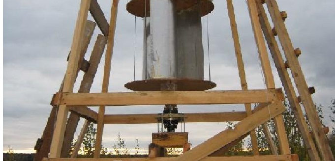
Installing an axis with blades on the tower

Visual image of the installation of the vertical axis of rotation on the roof of the building
- Turbine with vertical blades.
- The axis stabilization platform with a two-row ball bearing.
- Stretch marks steel cable Ø 5mm.
- Vertical axis, steel pipe Ø 40-50mm, wall thickness not less than 2 mm.
- Rotation speed controller lever.
- The blades of the aerodynamic regulator are made of plywood or plastic with a thickness of 3-4 mm.
- The thrust that is regulated by the speed of rotation, the number of revolutions.
- Cargo whose weight sets the speed of rotation.
- The pulley of the vertical axis for belt transmission is widely used by the cycling rim from the wheel, without a camera and tires.
- Support bearing.
- Pulley on the axis of the generator rotor.
At the bottom end of the axis, the pulley for the belt transmission or gear for the gearbox is attached, this is necessary to increase the rotor speed. Practice shows that at wind speed 5 m / s Rotation of a shaft with horizontal blades from the barrel will not be more than 100 rpm. At wind speed, 8-10 m / s rotation reaches up to 200 m / s. This is very little so that the generator gives the necessary power to charge the battery.
Reducer As a ratio of 1:10 allows you to achieve the necessary speed of rotation.

Installing belt pulleys
Low-speed generator
To convert mechanical rotational energy to electricity, the easiest way to use automotive generators. But ordinary generators from passenger cars for wind turbines are not recommended due to the presence of brushes in their design. Graphite brushes remove the current, binding on the rotor, during operation they are erased and require replacement. In addition, such generators are highly coherent, to produce a voltage of 14 V with current to 50a, 2,000 and more revolutions are required.
More efficient generators for wind turbors from tractors and buses. 964.3701 with magnetic excitation of windings. They do not have brushes, work on lower revs. Generator G288A.3701 has three phases, used to power vehicles together with a battery. It has good characteristics For use in wind turbine systems:
- produces voltage 28 V;
- the built-in rectifier issues a constant current to 47 A;
- output power up to 1.3 kW;
- at idle rotation 1200 rpm;
- with a current load in 30A, 2100 rpm.
The generator has suitable dimensions and mass:
- total weight 10 kg;
- diameter 174 mm;
- length 230 mm.

MAZ generator - 24V
Generators of this type are used on the transport of KAMAZ, the Urals, Kraz, MAZ with engines of the Yamz 236, 238, 841, 842 and ZMZ 73 engine. In order to save the finance, you can buy a generator at the point of disassembly. To generate greater power of electricity at low revs, you can make a generator with your own hands on nourifying magnets, but this is a separate topic and requires a more detailed description.
Sequence of assembly
- First of all, the tower or the design of the fastening of the generator on the roof of the building is mounted. The vertical axis is fastened with bearings with bearings, blades are installed.
- After installing the axis with the blades on the bottom, the pulley for belt transmission is recorded.
- At the level of the axis pulley, to a specially prepared platform, a generator with a pulley for a belt on the Rotor shaft is attached. The pulses of the generator and the axis with blades must be installed at one level.
The pulley diameter on the axis should be about 10 times larger pulley diameter on the generator shaft. Based on the conditions that the estimated wind speed is about 10 m / s, gives the speed of rotation of the axis to 200 rp.
Formula is used:
WR \u003d WOS X DOSD, where
- WR is the rotational speed of the generator pulley;
- DOS - Pulley diameter on the vertical axis;
- d - pulley diameter on the generator rotor shaft;
- WOS is the speed of rotation of the pulley vertical axis.
WR \u003d 200 OBM x 500mm / 50 mm \u003d 2000 rpm - sufficient rotation speed so that the generator of the selected type displays the necessary power.
- The belt is stretched, for this, in the fastening platform, the generator should have a slot, like on fastening the car.
- The output wires of the generator are connected to the battery terminals.
These generators have built-in rectifiers, a permanent current at the output, so the positive red wire is attached to the "+" terminal, and the minus wire is to the minus terminal.
- The input of the 24V / 220V inverter is connected to the battery, also in compliance with polarities.
- The output of the inverter is connected to the chain with the load.
Video. Wind generator with his own hands.
Having necessary materials, practical skills of fitter work, using ready-made automotive generators with magnetic excitation windings, the wind generator is easy to install with your own hands. For the manufacture of a generator of greater power on nourified magnets, deeper knowledge in electrical engineering and electrical assembly skills will be required. This is one of the most simple ways Collect wind generator with your own hands.