Wind generator from a fan. Homemade for heating a small house or room
In this article I will tell you how to make an engine - a Bedini generator from a computer cooler. This device model is one of the lowest power, but at the same time it is very convenient to use, cheap and easy to manufacture. It is very convenient to conduct experiments with the model. It takes up very little space and is easy to maintain. I will tell you the best, in my opinion, way of making it.
You will need: Transistor 2N3055 TO-3; Diode 1 N 4001 and 1 N 4007; Resistor 47 Ohm - 100 Ohm (I recommend 51 Ohm, 1W -2W); 1kΩ trim resistor (I recommend R-17N1-B1K, L15KC or 3296W-1-102LF potentiometer 1K(SP5-2VB)); computer cooler (I took JF0925S1H, fan 12V, 92x92x25mm), but in general it doesn’t matter what kind of stickers there will be on the cooler; terminal blocks, crocodiles. You can buy all this at a radio store, electrician, or take it out of radio devices; I bought it at the Voltmaster store. I really liked the store, their prices are an order of magnitude lower than others. You also need a neon light bulb NE - 2. Pull it out of the starter to fluorescent lamp, radiator (you can take a piece of aluminum, you can pull it out from some unnecessary radio equipment), a piece of plywood or organic glass 16.5mm * 15.5mm and other small fittings (single-core and stranded wires, bolts, nuts).

Here is the diagram to assemble:

Here is a visual diagram:


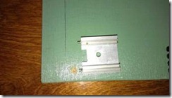
Now attach the transistor to the heatsink and the heatsink to the base.


The next step is to prepare the cooler. Remove the sticker, then the rubber plug on the back. Using a small screwdriver or tweezers, remove the cotter pin (circlip). Remove the blades.

You will see 4 coils attached to the chip with three legs. Grab the core of the coils with pliers and insert a small screwdriver into the space for the blade axle. Holding everything firmly by the core, hit the screwdriver with a hammer. The microcircuit with coils must separate from the entire structure.

Unsolder the coils from the microcircuit. The chip has 3 pins, you must insert a cutoff pin as the fourth pin. There are 2 wires soldered to one of the legs, unsolder one and solder it to the new leg so that there is one wire going to each leg.

Place the coil assembly back onto the axle, solder 4 different colored wires and lead them out.

Scope of application
It would seem that it would be easier to make a wind generator using a fan as a basis? However, several obstacles will stand in the way of such a technical transformation. This article will tell you how to overcome them, and what a wind power station made from a fan can be used for.
It’s worth making a reservation right away: you shouldn’t expect that the fruit of your labors will be a unit that can charge industrial batteries or heat buildings.
Charging a mobile phone, or operating a small LED illuminator - approximately such tasks can be solved by a wind generator, which is, so to speak, a product of deep processing of a fan.
Why do such externally similar devices require effort to transform into each other? There are technical explanations for this that would be worth considering.
Differences
Design features of electric motors and generators Electron movement electricity
, occurs in a conductor under the influence of a changing external magnetic field. Electric motors are designed similarly, only in the reverse order - a force acts on moving charged particles in a magnetic field, which forces the conductor to change its position in space, i.e. causes the rotor to move. In both generators and engines, this same magnetic field is created in the stator or rotor, depending on the model, permanent magnets
or electromagnets (excitation windings). If the motor attracts iron objects, it is on permanent magnets. This option is optimal from the point of view of using it as a generator, since it does not require any modernization.
“Using a motor with excitation windings to generate electricity will be more difficult, because you will have to provide power to these same windings. And this will significantly complicate the design.”
This is how a car generator actually works. 12V is supplied to the rotor through the “tablet”, brushes and slip rings. The magnetic field it creates rotates along with the rotor. It is this that creates an electric current in the stator winding (of course, more current is generated than consumed, otherwise why would a generator be needed).
Sometimes it is proposed to remove the windings from the rotor in such a case and glue in neodymium permanent magnets instead of wire (in this case no current is needed), but this is a topic for a separate article.
Features of blade geometry
Since the design of the fan meets the goal of pushing a mass of air, but, on the contrary, is driven by currents of air masses, the geometry will differ slightly. The angle of attack of the tips of the blades of both types differs little. 
The closer you move to the center, differences are observed.
Wind turbine propeller:
The section of the blade at the center practically does not participate in energy generation, since it moves many times slower than the entire blade, so it is made with an angle of attack equal to zero so that air masses can easily pass without creating congestion in the form of turbulence. A stationary fan does not need to change the angle of attack of the blade.
Since the overall geometry is similar, the fan propeller will also work as a wind generator.
Rotational speed
It is unlikely that at least one fan, when exposed to wind, will produce the same speed as when plugged into the network. Therefore, you should not hope that a 100-watt wind generator made from a 12V fan will produce the same voltage and provide 100-watt operation to consumers.
Manufacturing examples
From a children's toy battery-powered fan
Making such a wind generator is as easy as shelling pears. The toy uses an electric motor most often of 1.5 or 4.5 volts with independent excitation from permanent magnets. There is a ready-made screw. You need to take out the batteries, connect the wires to the + and − contacts, place the fan in the air flow, turn it on, and you can measure the characteristics of the generated current at the contacts.
In order for such a wind generator to work better, it would not hurt to add power to the propeller blades, for example, with pads cut from plastic pipe in the shape of petals. Well, you will have to equip the unit with some other elements required for an electric windmill. 
The fan will have to be protected from precipitation with a special casing and mounted on a movable frame. The movable fastening of the frame to the mast must include a contact-brush mechanism (without it, the current cannot be transmitted down). The opposite end of the frame is equipped with a stabilizer; its task is to turn the wind generator towards the air flow.
What you can count on if the engine is 4.5V is 2.5...3V maximum, not even enough to charge a phone (usually 5V). But the power supply of LEDs, which, for example, can be used to mark the boundaries of entrance gates or illuminate boundaries garden path, such a device, with sufficient wind, is quite capable of providing.
From the CPU cooler fan (cooler)
This fan most often has a 12V motor, as in the previous example with permanent magnets, and its transformation into a wind generator occurs in the same order.
The differences are that:
- the cooler blades are no good initially - the propeller needs a new one;
- the generated current at a certain wind speed is quite enough to charge an Android or 5V tablet (using a controller in this case cannot be avoided and a regular car charger is best suited).
From a car engine radiator cooling fan
The option is more complicated, but if the previous options were initially considered as toys, then this design can have quite tangible returns. The wind generator in question can serve, for example, to charge a 12V battery. The electricity stored in the battery, passed through a 12/220 converter, can be used as a home network.
The design uses a 24V fan motor. The blades are shortened, leaving only the fragments necessary for attaching new ones - cut from PVC pipes(it will not be possible to use PVC bottles for these purposes - due to their low rigidity, they will simply be bent by the wind).
The blades are cut out approximately according to the same pattern as in the photo. 
The number of blades can be any; the most commonly used options are 3, 4 or 6.
The wind generator is assembled according to the classical scheme (Fig. 3). The voltage generated by it at a moderate 4...7 m/s will be more than 12V, which will allow charging the battery. IN electrical circuit a diode must be added so that if there is no wind, the power plant does not turn into a fan on the mast.
A battery charging controller, which regulates the charging current and opens the circuit when charging is complete, will also help. You can do without it, but then you will have to constantly monitor the charging process and adjust it manually.
Hello everybody! There are many schemes on the Internet high voltage generators differing in power, assembly complexity, price and availability of components. This homemade product is assembled from almost waste parts; anyone can assemble it. This generator was assembled, let’s say, for informational purposes and all kinds of experiments with electricity high voltage. The approximate maximum of this generator is 20 kilovolts. Since this generator does not use mains voltage as a power source, this is an additional plus from a safety point of view.

Everything in the photo necessary details, for assembling a high-voltage generator.
For assembly you will need:
Ignition coil from VAZ
Cooler with hall sensor
"N" channel mosfet
100 Ohm and 10 kOhm resistors
Connecting insulated wires
Soldering iron
Terminal block (optional)
Heatsink for mosfet
Several screws
Plywood base for fastening parts

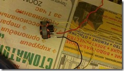
If anyone is interested, I’ll try to tell you more. A computer cooling cooler or similar 12 volt is used as a pulse generator, but with one condition - it must have a built-in hall sensor. It is the hall sensor that will generate pulses for the high-voltage transformer, which, in in this case, an ignition coil from a car is used. Choosing a suitable fan is very simple; as a rule, it has three inputs.

The photo shows the presence of three conclusions. The standard color is red pin plus power, black – common (ground) and yellow – output from the hall sensor. When power is applied to the fan, the output ( yellow wire) we get pulses, the frequency of which depends on the speed of the electric motor of a given cooler and the higher the voltage, the higher the frequency of the pulses. The voltage should be increased within reasonable limits - approximately 12-15 volts, so as not to burn the cooler and the entire circuit. The resulting pulse signal must be applied to the ignition coil, but it must be amplified.

I used “N” channel as a power switch field-effect transistor(mosfet) IRFS640A others with similar parameters are suitable, or approximately for a current of 5-10 amperes and a voltage of 50 volts for reliability. Mosfets are present in almost all modern electronic circuits, be it a computer motherboard or a starting circuit energy saving lamp, which means you won’t have any problems finding the right one.

The ignition coil from VAZ “classic” B117-A cars has three terminals. The central one is a high-voltage output, “B+” is positive 12 volts, and the general “K” is probably not marked.
Initially, the circuit consisted of three components: a cooler, a mosfet and a coil, but after a short time of operation it broke down, as either the mosfet or the hall sensor failed. The output is to install 100 Ohm resistors to limit the inrush current from the Hall sensor to the gate, and a 10 kOhm pull-up resistor to turn off the mosfet in the absence of a pulse.

When assembling the circuit, the transistor should be installed on a radiator, preferably using thermal paste, since the heating during operation is significant.

I used the connector from the cooler as a terminal block to connect the mosfet. As a result, there is no need to solder the transistor; to connect or replace it, it is enough to connect the block to the terminals of the transistor.

The fan was secured on top of the radiator using two self-tapping screws. As a result, it turned out that the cooler plays a dual role - as a pulse generator and as additional cooling.
Vladimir
Well, there are a lot of articles on Tyrnet about “perpetual motion machines on magnets” and there is no point in touching on this topic - until one of these authors assembles a working model that would at least produce something at the output (at least symbolic microvolts!).
In the meantime, something is preventing the authors from doing this - there is no special alloy for magnets, there is no special equipment for their intricate magnetization, etc. and so on!
But it’s worth discussing what can be analyzed with basic knowledge and experience - at the level of pioneer young radio amateurs (from which, for example, I myself came out - many decades ago). Unfortunately, the author did not even go through this primary school, and therefore it will be useful for him to familiarize himself with Not big amount elementary facts that I will present.
To find out what the cooler will produce (or, more precisely, will not produce anything) - just blow it out with a vacuum cleaner (as already suggested) and connect a tester (multimeter) to the terminals. As an option, you can fasten a pair of identical coolers with one (blowing) side facing each other. “glue” them together with small pieces of plasticine or tighten them with a pair of rubber bands. Apply 12 V to one cooler, and take readings from the terminals of the second by connecting a tester.
It is clear that it will not show anything - neither variable nor constant, or it will be a few millivolts (as the most the best option) induced on the switched windings and which may pass through the transitions of the transistors. As already mentioned, there is a commutator microcircuit that, through transistor switches, alternately supplies voltage to several windings, the magnetic field of which interacts with the permanent magnets in the rotor (turntable). It is clear that even the smallest amount of what can pass through the junctions of transistors will not be direct current, since there is no filtering of the pulsating current (in the form of electrolytes).
In general, in order to understand what kind of power can be obtained from such devices, it is important to know that reversible electric motor-generators (and any classical electric motor can work as a generator) cannot, by definition, provide more than the power that they themselves consume as electric motors.
Such coolers have a power consumption of 1.5-2 W. and when it operates in generator mode, its power will be even less than what it consumes itself, like an electric motor.
It is clear that such experiments can be carried out with ordinary “motors” without any electronic switches inside.
I remember that in the Young Technician of the 70s, a homemade product was described from a children’s motor from a toy, on which a generator was assembled with a load on a light bulb from a lantern. In this case, it was proposed to install a propeller on the shaft. And as the author of the article claimed, when this “windmill” was installed on a bike, it generated enough power to illuminate the road at night.
Personally, I think that the power of that generator would be quite enough to power a modern ultra-bright LED (again, for this it was necessary to install a rectifier and filter the current), but to power an incandescent lamp with a current of 0.25-0.35 A (namely, these were the ones in flashlights) is clearly not enough.
So the author proposes to get from a cooler a power of 2 W - the power to power three lamps of 70 W each - i.e. 210 W?
But as is already clear, there will be no voltage at its output, neither 1V, nor even less 12V, and especially constant!
Next, the author suggests using a 220 V converter. But from the photo you can see that this is a regular power supply with a transformer! And what is a classic transformer power supply for 10-12 W - and this is exactly the Chinese power supply shown in the photo (note 10-12 W, but we need a power of 210 W!)?
So, in a simplified form, this is a transformer (with a step-down transformation ratio), a rectifier ( diode bridge) and filter (electrolytic capacitors). Most likely there is no stabilizer in it.
Well, just by presenting the circuit of this power supply, it is completely clear that by applying a constant voltage to its output (which, as the author naively believes, should appear at the cooler terminals), you will not get anything! It doesn’t matter whether the bridge diodes are turned on in the forward or reverse direction... In the first case, the winding will receive D.C., but in the second - no. But at the same time, no voltage will appear at the output of the transformer - neither DC nor AC! And if you remove the diodes, you won’t get anything, because in order for a transformer to be made from 12 V>220 V, you need to apply AC voltage to it!
Again, do not forget that we have a power supply (by appearance) no more than 12W, which means its output power (in inverse mode) will not exceed 12W!
The author, as I understand it, does not understand the difference between conventional transformer power supplies and converters, but you need to understand that if the converter converts 220 V alternating voltage into low direct voltage (for example, like computer power supplies), then they cannot be used to obtain AC voltage 220 V from low DC voltage- only by “turning it on in reverse,” as the author naively believes. For these purposes, you can only use a converter that was originally created to convert from constant, low-voltage to alternating-mains power (such as a UPS for computers). And this is completely understandable to any radio engineer - since circuit solutions(methods) for obtaining the required output voltages are different!
Wind is free energy! So let's use it for personal purposes. If the creation of a wind farm in industrial scale this is very expensive, because in addition to the generator, a number of studies and calculations need to be carried out, the state does not bear such expenses, and for some reason investors in the countries of the former USSR are not of particular interest. Then privately you can make a mini-windmill for your own needs. It is worth understanding that the project of converting your home to alternative energy is a very expensive undertaking.
As already mentioned: you need to make long-term observations and calculations in order to select the optimal ratio of the sizes of the wind wheel and the generator, suitable for your climate, wind rose and average annual wind speed.
The efficiency of a wind power plant within one region can differ significantly, this is due to the fact that wind movement depends not only on the climate zone, but also on the terrain.

However, you can find out what wind power is with minimal costs by assembling a budget installation to power a low-power load, such as a smartphone, light bulbs or radio. With the right approach, you can provide electricity small house or summer cottage.

Let's look at how you can make a simple wind-electric installation with your own hands.
Low-power windmills made from improvised means
A computer cooler is a brushless motor, which in its original form is of no practical value.

It needs to be rewinded, since in the original the windings are connected inappropriately. Wind the coils one by one:
Clockwise;
Counterclock-wise;
Clockwise;
Counterclock-wise.

Adjacent coils need to be connected in series, or even better, wind with one piece of wire moving from one groove to another. In this case, select the thickness of the wire arbitrarily; it will be better if you wind as many turns as possible, and this is possible when using the thinnest wire.
The output voltage from such a generator will be variable, and its value will depend on the speed (wind speed), install a diode bridge of Schottky diodes to rectify it to constant, ordinary diodes will do, but it will be worse, because the voltage across them will drop from 1 to 2 volts.
Lyrical digression, a little theory
Remember the magnitude of the EMF is equal to:
where L is the length of the conductor placed in a magnetic field; V is the rotation speed of the magnetic field;
When upgrading a generator, you can only influence the length of the conductor, that is, the number of turns of each coil. The number of turns determines the output voltage, and the thickness of the wire determines the maximum current load.
In practice, it is impossible to influence wind speed. However, there is also a way out of this situation; after finding out the typical wind speed for your area, you can design a propeller suitable for the speed of a wind-electric installation, as well as a gearbox or belt drive to ensure sufficient speed to generate the required voltage.
IMPORTANT: Faster does not mean better!!! If the rotation speed of the wind generator is too high, its service life will be shortened, the lubrication properties of the rotor bushings or bearings will deteriorate, and it will jam, and most likely, a breakdown of the insulation of the windings in the generator will occur
The generator consists of:

Increasing the power of the generator from a computer cooler
Firstly, the more blades and wheel diameter the better, so take a closer look at 120mm coolers.
Secondly, we have already said that the voltage also depends on the magnetic field; the fact is that high-power industrial generators have excitation windings, and low-power ones have strong magnets. The magnets in the cooler are extremely weak and do not allow achieving good results from the generator, and the gap between the rotor and stator is very large - about 1 mm, and this is with already weak magnets.

The solution to this problem is to radically change the design of the generator. More precisely, the cooler will only require an impeller; as the generator itself, we can use a motor from a printer or any other household appliance. Most common brushed motors with excitation from permanent magnets.
As a result it will look like this.

The power of such a generator is enough to power LEDs and a radio receiver. It will not be enough to recharge the phone; the phone will display the charging process, but the current will be extremely small, up to 100 Amperes, with a wind of 5-10 meters per second.
Stepper motors as a wind generator
Stepper motors are very often found in computer and household appliances, in various players, floppy drives (old 5.25” models are interesting), printers (especially dot matrix ones), scanners, etc.
These motors can operate as a generator without modification; they consist of a rotor with permanent magnets and a stator with windings, typical diagram Connecting a stepper motor in generator mode is shown in the figure.

The circuit contains a 5 Volt linear stabilizer, type L7805, which will allow you to connect without fear Cell phones to such a windmill to charge them.

The photo shows a generator made from a stepper motor with blades installed.
Engine in specific case with 4 output wires, the diagram is accordingly for it. An engine with such dimensions in generator mode produces approximately 2 W in low winds (wind speed about 3 m/s) and 5 m/s in strong winds (up to 10 m/s).
By the way, here is a similar circuit with a zener diode, instead of L7805. Allows you to charge Li-ion batteries.

Refinement of a homemade windmill
In order for the generator to work more efficiently, you need to make a guide shank for it and movably fix it on the mast. Then, when the wind direction changes, the direction of the wind generator will change. Then the next problem arises - the cable going from the generator to the consumer will twist around the mast. To solve this, you need to provide a moving contact. A ready-made solution is sold on Ebay and Aliexpress.

The lower three wires are stationary and go down, and the upper bundle of wires is movable; a sliding contact or brush mechanism is installed inside. If you don’t have the opportunity to buy, be smart and, inspired by the decision of the designers of the Zhiguli car, namely the implementation of a moving contact for the signal button on the steering wheel, and do something similar. Or use the contact pad from an electric kettle.

By connecting the connectors, you get a moving contact.
A powerful wind generator made from improvised means.
To get more power you can use two options:
1. Generator from a screwdriver (10-50 W);
The only thing you need from a screwdriver is a motor, the option is similar to the previous one, you can use fan blades as a screw, this will increase the final power of your installation.
Here is an example of such a project:

Pay attention to how a gear overdrive is implemented here - the wind generator shaft is located in a pipe, at its end there is a gear that transmits rotation to a smaller gear mounted on the engine shaft. An increase in engine speed also occurs in industrial wind power plants. Gearboxes are used everywhere.

However, in homemade conditions, making a gearbox becomes a big problem. You can remove the gearbox from the power tool, it is needed there to reduce the high speed on the shaft of the commutator motor to the normal speed of the chuck on a drill, or the grinder disk:
The drill has a planetary gearbox;
The angle grinder is equipped with an angular gearbox (it will be useful for installing some installations and will reduce the load on the tail of the wind turbine);
Gearbox from a hand drill.

This version of a homemade wind generator can already charge 12 V batteries, but a converter is needed to generate the charging current and voltage. This task can be simplified by using a car generator.

The advantage of such a generator is the ability to use it to charge car batteries; in principle, this is what it is designed for. Autogenerators have a built-in voltage regulator relay, which eliminates the need to buy additional stabilizers or converters.
However, car enthusiasts know that at low idle speeds, approximately 500-1000 RPM, the power of such a generator is low, and it does not provide the required current to charge the battery. This leads to the need to connect to the wind wheel through a gearbox or belt drive.
You can adjust the number of revolutions at normal wind speeds for your latitudes by selecting the gear ratio or using a properly designed wind wheel.
Useful tips

Perhaps the most convenient design for repeating a mast for a wind turbine is shown in the picture. Such a mast is stretched on cables attached to holders in the ground, which ensures stability.

Important: The height of the mast should be as high as possible, approximately 10 meters. At higher altitudes, the wind is stronger because there are no obstacles to it in the form of ground structures, hills and trees. Do not install a wind generator on the roof of your house under any circumstances. Resonant vibrations of fastening structures can cause destruction of its walls.
Take care of the reliability of the supporting mast, because the design of a windmill based on such a generator becomes significantly heavier and is already a rather serious solution that can provide autonomous power supply to a dacha with a minimum set electrical appliances. Devices that operate on 220 Volts can be powered from a 12-220 V inverter. The most common version of such an inverter is.

It is better to use diesel generators, incl. trucks, because they are designed to operate at low speeds. On average, a large truck diesel engine operates between 300 and 3,500 rpm.
Modern generators produce 12 or 24 Volts, and a current of 100 Amps has long become normal. Having carried out simple calculations, you can determine that such a generator will give you a maximum of up to 1 kW of power, and a generator from a Lada (12 V 40-60 A) 350-500 W, which is already a pretty decent figure.
What should a wind wheel be like for a homemade wind turbine?
I mentioned in the text that the wind wheel should be large and with a large number of blades, in fact this is not the case. This statement was true for those micro-generators that do not pretend to be serious electric machines, but rather copies for reference and leisure.
In fact, designing, calculating and creating a wind wheel is a very difficult task. Wind energy will be used more rationally if it is done very accurately and the “aviation” profile is ideally designed, and it should be installed with a minimum angle to the plane of rotation of the wheel.
Real power of wind wheels with the same diameter and different amounts The blades are the same, the only difference is their rotation speed. The fewer wings, the more revolutions per minute, with the same wind and diameter. If you are going to achieve maximum speed, you must mount the wings as accurately as possible with a minimum angle to the plane of their rotation.

Check out the table from the 1956 book “Homemade Wind Power Plant” ed. DOSAAF Moscow. It shows the relationship between wheel diameter, power and rpm.
At home, these theoretical calculations are of little use; amateurs make wind wheels from improvised means, using:
Sheets of metal;
Plastic sewer pipes.
You can assemble a high-speed 2-4 bladed wind wheel with your own hands from sewer pipes, in addition to them, you need a hacksaw or any other cutting tool. The use of these pipes is determined by their shape; after cutting, they have a concave shape, which ensures high responsiveness to air flows.

After trimming, they are secured with BOLTS to a metal, textolite or plywood blank. If you are going to make it from plywood, it is better to re-glue and screw together several layers of plywood on both sides with screws, then you will be able to achieve rigidity.

Here is an idea for a two-blade solid impeller for a stepper motor generator.

conclusions
You can make a wind-electric installation starting from low power - units of Watt, to power individual LED lamps, beacons and small equipment, up to good power values in kilowatt units, accumulate energy in a battery, use it in its original form or convert it to 220 Volts. The cost of such a project will depend on your needs; perhaps the most expensive element is the mast and batteries, which can range from $300-500.