Flashlight era diagram. We are restoring and bringing to mind a Chinese flashlight. Alteration of the battery charging mode indication circuit
Dedicated to all those who have similar LED lights.
A typical problem with the latter is a 4 Volt lead (AGM) battery that "unexpectedly" stops working.
There was a review recently with a solution to a similar problem. ...
I took a slightly different path, later it will be clear why.
First, a little about lanterns:
Budget lights of decent size and mediocre performance. But they continue to be bought and used. The flashlight contains a variety of super bright 3-5mm LEDs. 

The LEDs are usually connected in parallel, through current limiting resistors. 
The heart of the flashlight is a lead-acid (AGM) rechargeable battery with a capacity of up to 4.5Ah. 
The unpretentiousness of the battery can be considered a positive point. Possibility of recharging at any time and work at subzero temperatures. The last moment in my alteration is not taken into account, since the operation of the flashlight at a significant negative temperature is not planned.
Looking ahead, I will say that it took about 2 hours to modify the lantern.
We open the lantern and remove the dead battery:
To begin with, I measured the current consumption at a battery voltage of 3.84 V:

Current limiting resistors are installed in series with the LEDs. Due to the changed voltage of the flashlight, it would be possible to lower the resistances of the resistors, but I did not do this. The brightness dropped slightly, you can put up with this, and it's troublesome in time.
At a voltage of 4.2V, the current exceeded 1 A. This was the starting point for solving the problem. The use of a kit of a cheap power bank is eliminated due to the inability of the latter to provide the required current.
The solution was on the surface:
Two board options, one with overdischarge protection, the other without protection: 
A little about the boards. The controller is one of the most common TP4056. I used a similar board. Controller documentation. The controller provides a charge current of up to 1 Ampere, so you can roughly calculate the charging time for the batteries.
Which board to use in your flashlight depends on the type of 18650 cells used. If there is overdischarge protection, then the one on the right. Otherwise, you can assign the function of protecting the battery to the board with which it copes remarkably well. The boards differ from each other in the presence of additional parts, such as the DW01 discharge controller and the 8205 power switch (double field-effect transistor) for disconnecting the battery from the load at the right time or protecting against overcharging.
There is a lot of space inside, you can install at least a dozen batteries, but for the test I managed one. 
The latter was removed from an old laptop battery and tested on an IMAX B6 charger: 

With a discharge current of 1 Ampere, the residual capacity is 1400 mAh. This is enough for about an hour and a half of continuous operation of the flashlight.
Trying to connect the battery to the board:

The wires to the battery must be soldered carefully, without overheating the latter. If you are not sure, you can use the battery holder. 
It is also advisable to observe the color differentiation of the pants, use wires of different colors to connect the power.
We connect the board via a micro USB cable to the power supply:

The red LED lit up, the charge went.
Now you need to install the charge controller board into the flashlight. There are no special fasteners, so we make the collective farm using the superglue everyone loves. 
Gluing fingers at least once is the sacred duty of everyone who used it.
We make a bracket from a suitable metal plate (an element from a children's metal designer will do). 
In order to avoid short circuits, we use insulating material. I used a piece of heat shrink tubing.
I fixed the board by first connecting the wires that went earlier to the lead battery:

From the outside it looks like this:
Small defects are visible on the sides of the connector. They are corrected as follows: the hole or gap is covered with baking soda and then 1-2 drops of superglue. The glue sets instantly. After 30 seconds, you can file the surface with a file.
We fix the battery inside in any way possible. I applied a sealant, someone is more comfortable with a glue gun.
The opening of the charging connector will later be covered with a rubber cap.
We collect and include:
Working.
Upd: If you plan to connect several batteries in parallel, then before connecting, in order to avoid damage to the latter, it is necessary to bring all batteries to a single EMF (simple voltage).
Findings: Costs for money are about 100 rubles and 2 hours of time. I don't take the battery into account, I used a semi-dead one with a large internal resistance. I get a working lamp. The procedures I describe are not a panacea; there are other options for modifying the flashlights. The indication of the charging process / readiness was not displayed on the case. The blue / red LEDs glow through the housing.
By the way, the board can have any connector you like mini or micro USB. It all depends on the availability of the correct cables. Among other things, we still have a power supply unit on hand for charging a lead-acid battery - it will be possible to usefully attach it somewhere.
Pros:
Work lamp, less weight (although this is a minor fact). You can charge in any accessible place with a USB charger or a computer.
Minuses:
The battery is afraid of frost, less brightness (by about 10-15%) in relation to the factory version. At the end of the discharge, the brightness drops, noticeably by eye. To solve this problem, you can install a larger (or more) battery.
For safety and the ability to continue active activity in the dark, a person needs artificial lighting. Primitive people pushed the darkness apart, setting fire to tree branches, then invented a torch and a kerosene stove. And only after the invention of the prototype of the modern battery by the French inventor George Leclanche in 1866, and in 1879 by Thomson Edison of the incandescent lamp, did David Meisel have the opportunity to patent the first electric lantern in 1896.
Since then, nothing has changed in the electrical circuit of new lantern samples, until in 1923 the Russian scientist Oleg Vladimirovich Losev found a connection between luminescence in silicon carbide and a pn-junction, and in 1990, scientists failed to create an LED with a higher light output, allowing to replace a light bulb incandescent. The use of LEDs instead of incandescent lamps, due to the low power consumption of LEDs, made it possible to significantly increase the operating time of flashlights with the same capacity of batteries and accumulators, increase the reliability of flashlights and practically remove all restrictions on their area of \u200b\u200buse.
The LED rechargeable flashlight that you see in the photo came to me for repair with a complaint that the Lentel GL01 Chinese flashlight bought the other day for $ 3 does not shine, although the battery charge indicator is on.

External inspection of the lantern made a positive impression. High-quality casting of the case, comfortable handle and switch. The battery charging plugs are retractable, eliminating the need to store the power cord.
Attention! Care should be taken when disassembling and repairing the flashlight if it is connected to the mains. Touching exposed circuitry while connected to the mains may result in electric shock.
How to disassemble the Lentel GL01 LED rechargeable torch
Although the flashlight was subject to warranty repair, remembering my walks during the warranty repair of a failed electric kettle (the kettle was expensive and the heating element burned out in it, so it was not possible to repair it with my own hands), I decided to do the repair myself.

It turned out to be easy to disassemble the lantern. It is enough to turn the ring securing the protective glass by a small angle counterclockwise and pull it off, then unscrew several screws. It turned out that the ring is fixed to the body using a bayonet connection.

After removing one of the halves of the body of the flashlight, access to all its nodes appeared. On the left of the photo, a printed circuit board with LEDs is visible, to which a reflector (light reflector) is attached using three self-tapping screws. In the center there is a black battery with unknown parameters, there is only a marking of the polarity of the terminals. To the right of the battery is the printed circuit board for the charger and display. On the right is a power plug with retractable rods.

Upon closer examination of the LEDs, it turned out that there were black spots or dots on the emitting surfaces of the crystals of all LEDs. It became clear even without checking the LEDs with a multimeter that the flashlight does not shine due to their burnout.

There were also blackened areas on the crystals of two LEDs installed as a backlight on the battery charging indication board. In LED lamps and strips, one LED usually fails, and working as a fuse, protects the rest from burnout. And in the lantern, all nine LEDs went out of order at the same time. The battery voltage could not increase to a value that could damage the LEDs. To find out the reason, I had to draw an electrical schematic diagram.
Finding the cause of the flashlight failure
The electric circuit of the lantern consists of two functionally complete parts. The part of the circuit located to the left of the SA1 switch serves as a charger. And the part of the circuit shown to the right of the switch provides a glow.

The charger works as follows. The voltage from the 220 V household network is supplied to the current-limiting capacitor C1, then to the bridge rectifier assembled on VD1-VD4 diodes. From the rectifier, voltage is applied to the battery terminals. Resistor R1 serves to discharge the capacitor after removing the flashlight plug from the network. Thus, an electric shock from the discharge of the capacitor is excluded in the event of accidental hand touching of two pins of the plug at the same time.
The HL1 LED, connected in series with the current-limiting resistor R2 in the opposite direction with the upper right diode of the bridge, as it turned out, always lights up when the plug is inserted into the network, even if the battery is faulty or disconnected from the circuit.
The SA1 operating mode switch is used to connect individual groups of LEDs to the battery. As you can see from the diagram, it turns out that if the flashlight is connected to the mains for charging and the switch slider is in position 3 or 4, then the voltage from the battery charger also goes to the LEDs.

If a person turned on the flashlight and found that it was not working, and, not knowing that the switch engine must be set to the "off" position, which is not said in the operating instructions for the flashlight, connect the flashlight to the mains for charging, then at the expense voltage surge at the output of the charger, a voltage significantly higher than the calculated one will hit the LEDs. The current will flow through the LEDs in excess of the permissible current and they will burn out. With the aging of the acid battery due to the sulfation of the lead plates, the battery charge voltage increases, which also leads to burnout of the LEDs.
Another circuit solution that surprised me was the parallel connection of seven LEDs, which is unacceptable, since the current-voltage characteristics of even LEDs of the same type are different and therefore the current passing through the LEDs will also not be the same. For this reason, when choosing the value of the resistor R4 based on the maximum allowable current flowing through the LEDs, one of them may overload and fail, and this will lead to an overcurrent of the parallel connected LEDs, and they will also burn out.
Alteration (modernization) of the electric circuit of the lantern
It became obvious that the breakdown of the lantern was due to mistakes made by the developers of its electrical circuit diagram. To repair the flashlight and exclude its repeated breakdown, it is necessary to redo it by replacing the LEDs and making minor changes to the electrical circuit.

In order for the battery charge indicator to really signal its charging, it is necessary to turn on the HL1 LED in series with the battery. The LED needs a current of several milliamps to light up, and the current output from the charger should be about 100 mA.
To ensure these conditions, it is enough to disconnect the HL1-R2 chain from the circuit in the places indicated by the red crosses and install an additional 47 Ohm resistor Rd in parallel with it with a power of at least 0.5 W. The charge current flowing through Rd will create a voltage drop of about 3 V across it, which will provide the necessary current for the HL1 indicator to glow. At the same time, the connection point HL1 and Rd must be connected to pin 1 of switch SA1. In this simple way, the possibility of supplying voltage from the charger to the EL1-EL10 LEDs during battery charging will be excluded.
To equalize the magnitude of the currents flowing through the EL3-EL10 LEDs, it is necessary to exclude the resistor R4 from the circuit and in series with each LED connect a separate resistor with a nominal value of 47-56 Ohm.
Electrical diagram after revision
Minor changes made to the circuit have increased the information content of the charge indicator of an inexpensive Chinese LED flashlight and increased its reliability many times over. I hope that the manufacturers of LED lights, after reading this article, will make changes to the wiring diagrams of their products.

After the modernization, the electrical circuit diagram took the form as in the drawing above. If you need to illuminate with a flashlight for a long time and you do not need a high brightness of its glow, then you can additionally install a current-limiting resistor R5, due to which the operating time of the flashlight without recharging will double.
Repair of LED rechargeable flashlight
After disassembly, first of all, you need to restore the working capacity of the flashlight, and only then do the modernization.

Checking the LEDs with a multimeter confirmed their malfunction. Therefore, all the LEDs had to be evaporated and the holes for installing new diodes had to be freed from the solder.

Judging by their appearance, the board had lamp LEDs from the HL-508H series with a diameter of 5 mm. There were HK5H4U type LEDs from a linear LED lamp with similar technical characteristics. They came in handy for repairing the lantern. When soldering the LEDs to the board, you must remember to observe the polarity, the anode must be connected to the positive terminal of the battery or battery.
After replacing the LEDs, the PCB was connected to the circuit. The brightness of some LEDs was slightly different from others due to the common current-limiting resistor. To eliminate this disadvantage, it is necessary to remove the resistor R4 and replace it with seven resistors, connecting it in series with each LED.
To select the resistor that provides the optimal mode of operation of the LED, the dependence of the current flowing through the LED on the value of the series-connected resistance at a voltage of 3.6 V, equal to the voltage of the flashlight battery, was measured.
Based on the conditions for using the flashlight (in the event of power outages in the apartment), high brightness and illumination range were not required, so the resistor was chosen with a nominal value of 56 ohms. With such a current-limiting resistor, the LED will operate in light mode, and power consumption will be economical. If you want to squeeze out the maximum brightness from the flashlight, then you should use a resistor, as can be seen from the table, with a nominal value of 33 Ohm and make two modes of operation of the flashlight, including another common current-limiting resistor (in the diagram R5) with a nominal value of 5.6 Ohm.

To connect a resistor in series with each LED, you must first prepare the printed circuit board. To do this, you need to cut on it one by one any current-carrying track suitable for each LED and make additional contact pads. The current-carrying paths on the board are protected with a layer of varnish, which must be scraped off with a knife blade to copper, as in the photo. Then, tin the bare contact pads with solder.
It is better and more convenient to prepare a printed circuit board for mounting resistors and solder them if the board is fixed on a standard reflector. In this case, the surface of the LED lenses will not be scratched, and it will be more convenient to work.

Connecting the diode board after repair and modernization to the flashlight battery showed sufficient for illumination and the same brightness of all LEDs.

I didn't have time to repair the previous flashlight, when the second one got into repair, with the same malfunction. I did not find information about the manufacturer and technical characteristics on the body of the flashlight, but judging by the handwriting of the manufacture and the reason for the breakdown, the manufacturer is the same, the Chinese Lentel.

By the date on the body of the flashlight and on the battery, it was possible to establish that the flashlight was already four years old and, according to its owner, the flashlight worked flawlessly. Obviously, the flashlight lasted a long time thanks to the warning sign "Do not turn on while charging!" on a hinged lid covering the compartment, which contains a plug for connecting the flashlight to the mains to charge the battery.

In this model of the flashlight, the LEDs are included in the circuit according to the rules, a 33 Ohm resistor is installed in series with each. The size of the resistor is easy to find by color coding using an online calculator. Checking with a multimeter showed that all the LEDs are faulty, the resistors were also open-circuit.
Analysis of the reasons for the failure of the LEDs showed that due to the sulfation of the plates of the acid battery, its internal resistance increased and, as a result, its charging voltage increased several times. During charging, the flashlight was turned on, the current through the LEDs and resistors exceeded the limit, which led to their failure. I had to replace not only the LEDs, but all the resistors. Based on the above specified operating conditions of the flashlight, 47 Ohm resistors were selected for replacement. The resistor value for any type of LED can be calculated using an online calculator.
Alteration of the battery charging mode indication circuit
The lamp has been repaired, and you can start making changes to the battery charging indication circuit. For this, it is necessary to cut the track on the printed circuit board of the charger and display in such a way that the HL1-R2 chain from the side of the LED is disconnected from the circuit.

The lead-acid AGM battery was brought to a deep discharge, and an attempt to charge it with a standard charger was unsuccessful. I had to charge the battery using a stationary power supply with the function of limiting the load current. The battery was supplied with a voltage of 30 V, while at the first moment of time it consumed a current of only a few mA. Over time, the current began to increase and after a few hours it increased to 100 mA. After fully charged, the battery was installed in the flashlight.
Charging deeply discharged lead-acid AGM batteries after long-term storage with increased voltage allows them to restore their performance. I have tested the method on AGM batteries more than a dozen times. New batteries that do not want to be charged with standard chargers, when charged from a constant source at a voltage of 30 V, are restored to almost their original capacity.
The battery was discharged several times by turning on the flashlight in operating mode and charged using a standard charger. The measured charge current was 123 mA, with a voltage at the battery terminals of 6.9 V. Unfortunately, the battery was worn out and it was enough for the flashlight to work for 2 hours. That is, the capacity of the battery was about 0.2 A × hour, and for a long-term operation of the flashlight it needs to be replaced.

The HL1-R2 chain on the PCB was well placed, and it was necessary to cut just one conductor at an angle, as in the photo. The cutting width must be at least 1 mm. Calculation of the resistor rating and testing in practice showed that for the stable operation of the battery charging indicator, a 47 Ohm resistor with a power of at least 0.5 W. is required.

The photo shows a printed circuit board with a soldered current limiting resistor. After this modification, the battery charge indicator only lights up if the battery is actually being charged.
Modernization of the mode switch
To complete the repair and modernization of the lanterns, it is necessary to re-solder the wires at the switch terminals.
In the models of repaired lamps, a four-position slide-type switch is used to turn on. The average conclusion in the above photograph is general. When the switch slider is in the extreme left position, the common terminal is connected to the left terminal of the switch. When you move the switch slider from the extreme left position one position to the right, its general output is connected to the second output and with further movement of the slider sequentially to 4 and 5 outputs.

To the middle common terminal (see photo above), you need to solder the wire coming from the positive terminal of the battery. Thus, it will be possible to connect the battery to a charger or LEDs. You can solder a wire from the main board with LEDs to the first terminal, and a 5.6 Ohm current-limiting resistor R5 can be soldered to the second to enable the flashlight to switch to an energy-saving mode. Solder the lead from the charger to the rightmost terminal. This will exclude the possibility of turning on the flashlight while the battery is charging.
Repair and modernization
LED rechargeable flashlight "Foton PB-0303"
Another example from a series of Chinese-made LED lanterns, called Photon PB-0303 LED floodlight, came into my repair. The flashlight did not react when the power button was pressed, an attempt to charge the flashlight battery using a charger was unsuccessful.

The flashlight is powerful, expensive, costs about $ 20. According to the manufacturer, the luminous flux of the flashlight reaches 200 meters, the body is made of shock-resistant ABS plastic, the kit includes a separate charger and a shoulder strap.

Photon LED flashlight has good maintainability. To gain access to the electrical circuit, simply unscrew the plastic ring that holds the protective glass by rotating the ring counterclockwise while looking at the LEDs.

When repairing any electrical appliance, troubleshooting always begins with the power source. Therefore, the first thing was measured with a multimeter turned on in the mode, the voltage at the terminals of the acid battery. It was 2.3 V, instead of 4.4 V required. The battery has been completely discharged.
When the charger was connected, the voltage at the battery terminals did not change, it became obvious that the charger was not working. The flashlight was used until the battery was completely discharged, and then it was not used for a long time, which led to a deep discharge of the battery.

It remains to check the health of the LEDs and other elements. For this, the reflector was removed, for which six screws were unscrewed. On the printed circuit board there were only three LEDs, a chip (microcircuit) in the form of a droplet, a transistor and a diode.

From the board and the battery, five wires went into the handle. In order to understand their connection, it was necessary to disassemble it. To do this, use a Phillips screwdriver to unscrew the two screws inside the flashlight, which were located next to the hole into which the wires went.

To detach the handle of the flashlight from its body, it must be moved away from the fastening screws. This must be done carefully so as not to tear off the wires from the board.

As it turned out, there were no electronic elements in the pen. Two white wires were soldered to the terminals of the on / off button of the flashlight, and the rest to the connector for connecting the charger. A red wire was soldered to pin 1 of the connector (conditional numbering), which was soldered with the second end to the positive input of the printed circuit board. A blue and white conductor was soldered to the second contact, which was soldered to the negative side of the printed circuit board with the second end. A green wire was soldered to pin 3, the other end of which was soldered to the negative terminal of the battery.
Electrical circuit diagram
Having dealt with the wires hidden in the pen, you can draw an electrical schematic diagram of the Photon lantern.

From the negative terminal of the GB1 battery, the voltage is supplied to terminal 3 of the X1 connector and then from its terminal 2 through the blue-white conductor to the printed circuit board.
Connector X1 is designed in such a way that when the charger plug is not inserted into it, pins 2 and 3 are connected together. When the plug is inserted, pins 2 and 3 are disconnected. Thus, automatic disconnection of the electronic part of the circuit from the charger is ensured, excluding the possibility of accidental switching on of the flashlight while charging the battery.
From the positive terminal of the GB1 battery, voltage is applied to D1 (microcircuit-chip) and the emitter of the S8550 bipolar transistor. The CHIP performs only the function of a trigger that allows the button to turn on or off the EL LEDs (8 mm, white color, power 0.5 W, consumption current 100 mA, voltage drop 3 V.) without latching. When the S1 button is pressed for the first time from the D1 microcircuit, a positive voltage is applied to the base of the Q1 transistor, it opens and the supply voltage is supplied to the EL1-EL3 LEDs, the flashlight turns on. When the S1 button is pressed again, the transistor closes and the flashlight turns off.
From a technical point of view, such a circuit design is illiterate, since it increases the cost of the flashlight, reduces its reliability, and in addition, due to the voltage drop across the junction of the transistor Q1, up to 20% of the battery capacity is lost. Such a circuit solution is justified if it is possible to adjust the brightness of the light beam. In this model, instead of a button, it was enough to put a mechanical switch.
It was surprising that the EL1-EL3 LEDs in the circuit are connected in parallel to the battery like incandescent bulbs, without current-limiting elements. As a result, when switched on, a current flows through the LEDs, the value of which is limited only by the internal resistance of the battery and when it is fully charged, the current can exceed the permissible value for the LEDs, which will lead to their failure.
Checking the functionality of the electrical circuit
To check the operability of the microcircuit, transistor and LEDs from an external power source with a current limiting function, a DC voltage of 4.4 V was applied, observing polarity, directly to the power pins of the printed circuit board. The current limit was set to 0.5 A.

After pressing the power button, the LEDs lit up. After pressing again, they went out. The LEDs and the microcircuit with the transistor turned out to be working properly. It remains to deal with the battery and charger.
Recovery of an acid battery
Since the 1.7 A acid battery was completely discharged, and the standard charger was faulty, I decided to charge it from a stationary power supply. When connecting the battery for charging to a power supply with a set voltage of 9 V, the charging current was less than 1 mA. The voltage was increased to 30 V - the current increased to 5 mA, and after an hour under this voltage it was already 44 mA. Further, the voltage was reduced to 12 V, the current dropped to 7 mA. After 12 hours of charging the battery at a voltage of 12 V, the current rose to 100 mA, and the battery was charged with this current for 15 hours.

The temperature of the battery case was within normal limits, which indicated that the charging current was used not to generate heat, but to store energy. After charging the battery and finalizing the circuit, which will be discussed below, tests were carried out. The flashlight with the recovered battery illuminated continuously for 16 hours, after which the beam's brightness began to drop and therefore it was turned off.
Using the method described above, I had to repeatedly restore the performance of deeply discharged small-sized acid batteries. As practice has shown, only serviceable batteries, which have been forgotten for a while, can be restored. Acid batteries that have exhausted their resource cannot be restored.
Charger repair
Measurement of the voltage value with a multimeter at the contacts of the output connector of the charger showed its absence.

Judging by the sticker glued to the adapter case, it was a power supply unit delivering an unstabilized constant voltage of 12 V with a maximum load current of 0.5 A. Was an ordinary power supply used as a charger?
When the adapter was opened, a characteristic smell of burnt electrical wiring appeared, which indicated that the transformer winding had burned out.
The dialing of the primary winding of the transformer showed that it was open. After cutting the first layer of the tape that insulates the primary winding of the transformer, a thermal fuse was found, designed for a response temperature of 130 ° C. Testing showed that both the primary winding and the thermal fuse are defective.
Repair of the adapter was economically impractical, since it was necessary to rewind the primary winding of the transformer and install a new thermal fuse. I replaced it with a similar one, which was at hand, for a DC voltage of 9 V. The flexible cord with a connector had to be re-soldered from the burnt out adapter.

The photo shows a drawing of an electrical circuit of a burned-out power supply unit (adapter) of the Photon LED flashlight. The replacement adapter was assembled according to the same scheme, only with an output voltage of 9 V. This voltage is quite enough to provide the required battery charging current with a voltage of 4.4 V.

For fun, I connected the flashlight to a new power supply and measured the charging current. Its value was 620 mA, and this is at a voltage of 9 V. At a voltage of 12 V, the current was about 900 mA, significantly exceeding the load capacity of the adapter and the recommended charging current for the battery. For this reason, the primary winding of the transformer burned out from overheating.
Completion of the electrical circuit diagram
LED rechargeable flashlight "Photon"
To eliminate circuitry violations in order to ensure reliable and long-term operation, changes were made to the lantern circuit and the printed circuit board was revised.

The photo shows the electrical schematic diagram of the converted LED flashlight "Photon". Additional installed radio elements are shown in blue. Resistor R2 limits the battery charge current to 120 mA. To increase the charging current, you need to reduce the value of the resistor. Resistors R3-R5 limit and equalize the current flowing through the LEDs EL1-EL3 when the lamp is on. The EL4 LED with a series-connected current-limiting resistor R1 is installed to indicate the battery charging process, since the developers of the flashlight design did not take care of this.

To install current limiting resistors on the board, the printed paths were cut, as shown in the photo. The charge current limiting resistor R2 was soldered at one end to the contact pad, to which the positive wire from the charger was previously soldered, and the soldered wire was soldered to the second terminal of the resistor. An additional wire (yellow in the photo) was soldered to the same contact pad, designed to connect the battery charging indicator.

Resistor R1 and LED indicator EL4 were placed in the handle of the flashlight, next to the connector for the charger X1. The LED anode pin was soldered to pin 1 of the X1 connector, and to the second pin, the LED cathode, a current-limiting resistor R1. A wire (yellow in the photo) was soldered to the second terminal of the resistor, connecting it to the terminal of the resistor R2, soldered to the printed circuit board. Resistor R2, for ease of installation, could be placed in the handle of the flashlight, but since it heats up when charging, I decided to place it in a freer space.
When finalizing the circuit, MLT resistors with a power of 0.25 W were used, except for R2, which is designed for 0.5 W. EL4 LED is suitable for any type and color of light.

This photo shows the charging indicator while charging the battery. The installation of the indicator made it possible not only to monitor the battery charging process, but also to monitor the presence of voltage in the network, the health of the power supply and the reliability of its connection.
How to replace a burnt out CHIP
If suddenly the CHIP - a specialized microcircuit without marking in the "Photon" LED flashlight, or similar, assembled according to a similar scheme, fails, then to restore the flashlight's performance it can be successfully replaced with a mechanical switch.

To do this, you need to remove the D1 chip from the board, and instead of the Q1 transistor key, connect an ordinary mechanical switch, as shown in the above electrical diagram. The light switch can be installed instead of the S1 button or in any other suitable place.
Repair with modernization
LED Flashlight Keyang KY-9914
A visitor to the site Marat Purliev from Ashgabat shared in a letter the results of the repair of the Keyang KY-9914 LED flashlight. In addition, he provided a photo, diagrams, a detailed description and agreed to publish the information, for which I express my gratitude to him.
Thank you for the article "DIY repair and modernization of LED lamps Lentel, Foton, Smartbuy Colorado and RED".

Using the repair examples, I repaired and upgraded the Keyang KY-9914 flashlight, in which four of the seven LEDs burned out, and the battery was worn out. The LEDs burned out due to switching the switch while charging the battery.

In the revised wiring diagram, the changes are highlighted in red. I replaced the faulty acid battery with three used Sanyo Ni-NH 2700 AA rechargeable batteries in series, which were at hand.
After reworking the flashlight, the current consumption of the LEDs in two switch positions was 14 and 28 mA, and the battery charge current was 50 mA.
Repair and alteration of LED flashlight
14Led Smartbuy Colorado
The Smartbuy Colorado LED flashlight stopped turning on, although three AAA batteries were installed new.

The waterproof housing was made of anodized aluminum alloy and was 12 cm long. The flashlight looked stylish and was easy to use.
How to check the batteries for suitability in an LED flashlight
The repair of any electrical appliance begins with checking the power source, therefore, despite the fact that new batteries were installed in the flashlight, repairs should begin with checking them. In a Smartbuy flashlight, batteries are installed in a special container, in which they are connected in series using jumpers. In order to access the flashlight batteries, you need to disassemble by rotating the back cover counterclockwise.

Insert the batteries into the container observing the polarity indicated on it. The polarity is also indicated on the container, so it must be inserted into the body of the lantern with the side with the "+" sign.
First of all, it is necessary to visually check all the contacts of the container. If there are traces of oxides on them, then the contacts must be cleaned to a shine using sandpaper or scraped off the oxide with a knife blade. To avoid re-oxidation of the contacts, they can be lubricated with a thin layer of any machine oil.
Next, you need to check the suitability of the batteries. To do this, touching the probes of the multimeter, which is included in the DC voltage measurement mode, it is necessary to measure the voltage at the container contacts. Three batteries are connected in series and each of them should provide a voltage of 1.5 V, therefore the voltage at the terminals of the container should be 4.5 V.
If the voltage is less than the specified one, then it is necessary to check the correct polarity of the batteries in the container and measure the voltage of each of them individually. Perhaps only one of them sat down.

If everything is in order with the batteries, then you need to insert, observing the polarity, the container into the body of the lantern, screw the lid and check it for operability. At the same time, one should pay attention to the spring in the cover, through which the supply voltage is transmitted to the lamp housing and from it directly to the LEDs. There should be no traces of corrosion on its end.
How to check the health of the switch
If the batteries are good and the contacts are clean, but the LEDs are off, then you need to check the switch.

The Smartbuy Colorado has a push-button sealed switch with two fixed positions, a short lead from the positive terminal of the battery container. When the switch button is pressed for the first time, its contacts are closed, and when the switch is pressed again, they open.

Since batteries are installed in the lantern, you can also check the switch using a multimeter turned on in the voltmeter mode. To do this, rotate counterclockwise, looking at the LEDs, unscrew its front part and set it aside. Then, with one probe of the multimeter, touch the body of the flashlight, and with the second touch the contact, which is located deep in the center of the plastic part shown in the photo.
The voltmeter should show a voltage of 4.5 V. If there is no voltage, press the switch button. If it is working properly, then the voltage will appear. Otherwise, the switch must be repaired.
Checking the health of the LEDs
If in the previous steps of the search it was not possible to find a malfunction, then at the next stage you need to check the reliability of the contacts supplying the supply voltage to the board with LEDs, the reliability of their soldering and serviceability.

The printed circuit board with the LEDs sealed into it is fixed in the head of the flashlight using a steel spring-loaded ring, through which the supply voltage from the negative terminal of the battery container is simultaneously supplied to the LEDs along the body of the flashlight. The photo shows the ring from the side with which it presses the printed circuit board.

The retaining ring is fixed quite tightly, and it was possible to remove it only with the help of the device shown in the photo. Such a hook can be bent out of a steel strip with your own hands.

After removing the retaining ring, the printed circuit board with LEDs, which is shown in the photo, was easily removed from the head of the lantern. The absence of current-limiting resistors immediately struck, all 14 LEDs were connected in parallel and through a switch directly to the batteries. Connecting LEDs directly to a battery is unacceptable, since the amount of current flowing through the LEDs is limited only by the internal resistance of the batteries and can damage the LEDs. At best, it will greatly shorten their service life.

Since all the LEDs in the lantern were connected in parallel, it was not possible to check them using a multimeter included in the resistance measurement mode. Therefore, a DC supply voltage of 4.5 V was applied to the printed circuit board from an external source with a current limitation to 200 mA. All LEDs lit up. It became apparent that the flashlight malfunction was a poor contact of the printed circuit board with the retaining ring.
LED lamp current consumption
For interest, I measured the current consumption by LEDs from batteries when they were turned on without a current-limiting resistor.

The current was over 627 mA. The flashlight has LEDs of the HL-508H type, the operating current of which should not exceed 20 mA. 14 LEDs are connected in parallel, therefore, the total current consumption should not exceed 280 mA. Thus, the current flowing through the LEDs has more than doubled the nominal current.
Such a forced operation of LEDs is unacceptable, as it leads to overheating of the crystal, and as a result, premature failure of the LEDs. An additional disadvantage is that the batteries drain quickly. They will be enough if the LEDs do not burn out earlier, for no more than an hour of operation.

The design of the flashlight did not allow soldering current-limiting resistors in series with each LED, so I had to install one common one for all LEDs. The resistor value had to be determined experimentally. For this, the flashlight was powered from standard batteries and an ammeter was connected in series with a 5.1 ohm resistor in the positive wire break. The current was about 200 mA. When installing an 8.2 ohm resistor, the current consumption was 160 mA, which, as the test showed, is quite enough for good lighting at a distance of at least 5 meters. The resistor did not heat up to the touch, so any power will do.
Alteration of the structure
After the conducted research, it became obvious that for reliable and durable operation of the flashlight, it is necessary to additionally install a current-limiting resistor and duplicate the connection of the printed circuit board with LEDs and a fixing ring with an additional conductor.

If earlier it was necessary for the negative bus of the printed circuit board to touch the lamp body, then due to the installation of the resistor, it was necessary to exclude the touch. For this, a corner was ground off from the printed circuit board along its entire circumference, from the side of the current-carrying paths using a file.

To prevent the pressure ring from touching the current-carrying tracks when fixing the printed circuit board, four rubber insulators with a thickness of about two millimeters were glued to it with Moment glue, as shown in the photograph. Insulators can be made from any dielectric material, such as plastic or thick cardboard.

The resistor was previously soldered to the clamping ring, and a piece of wire was soldered to the extreme track of the PCB. An insulating tube was put on the conductor, and then the wire was soldered to the second terminal of the resistor.


After a simple DIY upgrade of the flashlight, it began to turn on stably and the light beam illuminated objects well at a distance of more than eight meters. Additionally, the battery life has more than tripled, and the reliability of the LEDs has increased dramatically.
Analysis of the reasons for the failure of refurbished Chinese LED lights showed that they all failed due to illiterately designed electrical circuits. It remains only to find out whether this was done on purpose in order to save on components and reduce the life of the flashlights (so that new ones would be bought more), or as a result of the developers' ignorance. I lean towards the first assumption.
Repair of LED lamp RED 110
A flashlight with a built-in acid battery from a Chinese manufacturer of the RED trademark got into repair. The lantern had two emitters: - with a beam in the form of a narrow beam and emitting diffused light.

The photo shows the appearance of the RED 110 flashlight. I liked the flashlight right away. Convenient body shape, two modes of operation, loop for suspension on the neck, retractable plug for charging. In the lantern, the section of LEDs for the scattered light shone, but not for the narrow beam.

For the repair, the black ring was first unscrewed, fixing the reflector, and then one self-tapping screw was unscrewed in the loop area. The body easily split into two halves. All parts were fixed on self-tapping screws and easily removed.

The charger circuit was made according to the classical scheme. From the network, through a current-limiting capacitor with a capacity of 1 μF, voltage was supplied to a rectifier bridge of four diodes and then to the battery terminals. The voltage from the battery to the LED of the narrow beam was supplied through a current-limiting resistor of 460 Ohm.

All parts were mounted on a single sided PCB. The wires were soldered directly to the pads. The appearance of the printed circuit board is shown in the photo.

10 side light LEDs were connected in parallel. The supply voltage was supplied to them through a common current-limiting resistor 3R3 (3.3 Ohm), although according to the rules, a separate resistor must be installed for each LED.

An external examination of the LED with a narrow beam of defects was not found. When power was applied through the flashlight switch from the battery, the voltage at the terminals of the LED was present, and it heated up. It became obvious that the crystal was broken, and this was confirmed by a dial tone with a multimeter. The resistance was 46 Ohm for any connection of the probes to the LED terminals. The LED was defective and needed to be replaced.

For the convenience of work, the wires were soldered from the LED board. After freeing the leads of the LED from the solder, it turned out that the LED is firmly held by the entire plane of the reverse side on the printed circuit board. For his department, we had to fix the board in the table temples. Next, install the sharp end of the knife at the junction of the LED with the board and lightly hit the knife handle with a hammer. The LED bounced off.
As usual, there was no marking on the LED body. Therefore, it was necessary to determine its parameters and select a suitable replacement. Based on the overall dimensions of the LED, the battery voltage and the size of the current-limiting resistor, it was determined that a 1 W LED (current 350 mA, voltage drop 3 V) is suitable for replacement. White LED6000Am1W-A120 was selected for repair from the "Reference Table of Popular SMD LED Parameters".

The printed circuit board on which the LED is installed is made of aluminum and at the same time serves to remove heat from the LED. Therefore, when installing it, it is necessary to ensure good thermal contact due to the tight fit of the back plane of the LED to the printed circuit board. To do this, before sealing, thermal paste was applied to the contact points of the surfaces, which is used when installing a radiator on a computer processor.

In order to ensure a snug fit of the plane of the LED to the board, you must first put it on a plane and bend the leads slightly upward so that they recede from the plane by 0.5 mm. Next, tin the conclusions with solder, apply thermal paste and install the LED on the board. Then press it to the board (it is convenient to do this with a screwdriver with the bat removed) and warm up the leads with a soldering iron. Next, remove the screwdriver, press it with a knife at the bend of the output to the board and warm it up with a soldering iron. After the solder has hardened, remove the knife. Due to the spring properties of the pins, the LED will be tightly pressed against the board.

When installing the LED, the polarity must be observed. True, in this case, if a mistake is made, then it will be possible to swap the voltage supply wires. The LED is soldered and you can check its operation and measure the current consumption and voltage drop.
The current flowing through the LED was 250 mA, the voltage drop was 3.2 V. Hence the power consumption (you need to multiply the current by the voltage) was 0.8 W. It was possible to increase the operating current of the LED by reducing the resistance of 460 Ohm, but I did not do this, since the brightness of the glow was sufficient. But the LED will work in a lighter mode, heat up less and increase the operating time of the flashlight from one charge.

Checking the heating of an LED that has been operating for an hour has shown effective heat dissipation. He heated up to a temperature of no more than 45 ° C. Sea trials have shown sufficient lighting range in the dark, more than 30 meters.
Replacing the acid battery in the LED flashlight
An acid battery that has failed in an LED flashlight can be replaced with a similar acid battery, lithium-ion (Li-ion) or nickel-metal hydride (Ni-MH) batteries of AA or AAA size.
In the repaired Chinese lanterns, lead-acid AGM batteries of various dimensions without marking with a voltage of 3.6 V were installed. According to the calculation, the capacity of these batteries is from 1.2 to 2 A × hours.

On sale you can find a similar acid battery from a Russian manufacturer for the 4V 1Ah Delta DT 401 UPS, which has an output voltage of 4 V at a capacity of 1 A × hour, costing a couple of dollars. For replacement, it is quite simple, observing the polarity, to re-solder the two wires.
After several years of operation, the Lentel GL01 LED lamp, the repair of which is described at the beginning of the article, was again brought to me for repair. Diagnostics showed that the acid battery has worn out.

A Delta DT 401 battery was purchased to replace, but it turned out that its geometric dimensions were larger than the faulty one. The standard flashlight battery had dimensions of 21 × 30 × 54 mm and was 10 mm higher. I had to modify the body of the flashlight. Therefore, before buying a new battery, make sure that it fits into the body of the flashlight.

The emphasis in the case was removed and a part of the printed circuit board was cut off with a hacksaw for metal, from which the resistor and one LED were previously soldered.

After the revision, the new battery was well installed in the body of the flashlight and now, I hope, will last more than one year.
Replacing the acid battery
AA or AAA batteries
If it is not possible to purchase a 4V 1Ah Delta DT 401 battery, then it can be successfully replaced with any three AA or AAA finger batteries with a capacity of 1 A × hour or more, which have a voltage of 1.2 V. connect three batteries in series, observing the polarity, by soldering wires. However, economically, such a replacement is impractical, since the cost of three high-quality AA batteries can exceed the cost of buying a new LED flashlight.
But where is the guarantee that there are no errors in the electrical circuit of the new LED flashlight, and you will not have to modify it either. Therefore, I believe that replacing the lead-acid battery in the modified flashlight is advisable, since it will ensure reliable operation of the flashlight for several more years. And it will always be pleasant to use a flashlight, repaired and modernized with your own hands.
How to repair a LED flashlight? Diagram of a Chinese flashlight with mains charging
Repair of LED lights - an overview of breakdowns, device and diagram
For the normal life of a person in the dark, he always needed light. With the advancement of technology, lighting sources have improved, from torches and kerosene lamps to rechargeable flashlights. A real revolution in the world of lighting technology was the creation of the LED, which immediately entered everyday life.
Modern LED lights are very economical, the light travels very far and is very bright. A huge share of such lithium flashlights on the modern market is made in China, they are very cheap and affordable. It is because of the low cost that breakdowns of various kinds often occur. In this article, we will consider the main problems of repairing LED lights and how to fix them yourself.
How does an LED flashlight work?
The classic device of flashlights is very simple (regardless of the type of housing, be it the Cosmos model or DiK AN-005). An LED is connected to the battery, the circuit is broken by the shutdown button. Depending on the number of LEDs, the number of light elements themselves (for example, the main lamp on the front and the auxiliary lamp in the handle), a stronger battery (or several), a transformer, a resistance are added to the circuit, and a more functional switch is installed (Fo-DiK flashlights) ...
Why does the flashlight break?
Now we will omit the problems associated with the improper operation of a Chinese flashlight - "I dropped it into a bowl of water, turned it on and off, but for some reason it does not shine." The low cost of flashlights is achieved by simplifying electrical circuits within the device. This allows you to save on components (on their quantity and quality). This is done so that people often buy new ones, and the old ones are simply thrown away, without even trying to fix them with their own hands.
Another point of economy is people working in production who are not qualified to do this kind of work. As a result, there are many small and large errors in the circuit itself, poor-quality soldering and assembly of components, which leads to constant repair of lamps. In most cases, all problems can be solved by correctly diagnosing them, and we will deal with this further.

The cause of the lamp breakage
Most likely, when the switch is switched, the LEDs do not want to light up due to a malfunction in the electrical circuit. The most common ones are:
- oxidation of battery or battery contacts;
- oxidation on the contacts to which the battery is connected;
- damage to the wires going both from the battery to the LED and vice versa;
- faulty shutdown element;
- lack of power in the circuit;
- breakage in the LEDs themselves.
Oxidation. Most often it occurs in old lanterns, which are often used in various weather conditions. Plaque that appears on the metal interferes with normal contact, due to which the flashlight on the batteries may flicker or not turn on at all. If oxidation is observed on a battery or accumulator, then you need to think about replacing.
How do I fix contacts? Light dirt is removed with your own hands with a cotton swab dipped in ethyl alcohol. When the contamination is very serious, even rust has gone along the body, the use of such a battery can be dangerous to health and life. In stores now you can find a sufficient number of new batteries and accumulators, even for old types of flashlights.

Take care of the environment - don't throw old batteries in the trash bin, you probably have collection points in the city for recycling.
Oxidation also forms on the contacts in the lamp itself. Here, too, you need to pay attention to their integrity. If the contamination can still be removed with a cotton swab and alcohol, stop at this option. For hard-to-reach places, you can use a cotton swab.
If the contacts are completely rusted or even rotten (which is not uncommon for an old flashlight), they will have to be changed. Ask an electronics store if there are similar contact elements (for at least ten years they are absolutely identical in all flashlights, with rare exceptions). If there are no similar ones, choose the most similar option. Armed with a thin soldering iron, they can be easily soldered.

Damaged wire contacts. In addition to the above-described places, contacts are present in the places where the wires of the electrical circuit are soldered. Cheap manufacturing, rush during assembly, and neglect of workers often lead to the fact that some wires are forgotten to solder altogether, so the LED flashlight does not work even if it is just out of the box. How do I repair my flashlight in this case? Look closely at the entire circuit, gently pushing back the wires with medical tweezers or other thin object. If a failed soldering is found, it must be restored using the same thin soldering iron.
The same can be done with flimsy joints, the characteristic condition of which is a torn, bare vein, barely attached to the place of adhesion. If you have enough time and resources, and you value this flashlight, you can methodically and efficiently solder all contacts in general. This will significantly increase the efficiency of such a circuit, protect exposed elements from moisture and dust (which is important if the flashlight is a headlamp), and in subsequent cases of repairing the flashlight, this item will be eliminated. Repair of small LED headlamps is carried out in exactly the same way, the dimensions are simply different.
Damaged wires. After you have made sure that the contacts are clean, you can start looking at all the wires in the circuit for damage or shorts. It is common for wiring to be damaged by an improperly installed housing cover, either during factory assembly or after a previous repair. Wire caught between two body parts and was cut or crushed while tightening the bolts. During the flow of current, the electrical circuit could overheat or even short-circuit, this will inevitably lead to the repair of the LED flashlight.

All broken sections must be soldered together to provide better conduction than simple twisting. Do not forget to insulate all exposed areas, it is best to use a thin heat shrinkage. Heavily damaged wires, which could already have rust, it is advisable to completely replace them with your own hands (select the appropriate core). After such a revision, old lanterns can shine much brighter - the modernization performed improves the current flow.
Defective switch. Also pay attention to the contacts of the wires with the switch terminals, troubleshoot. The easiest way to find out if your flashlight is not working because of a switch is to close the circuit without it. Exclude it from the circuit by directly connecting the battery-LEDs (you can also try from the network with the corresponding battery voltage). If they light up, change the switch. Perhaps it has already broken down mechanically from reusable use, the flashlight just turns off, and a defect in production is also possible. If the LEDs do not want to light up directly from the battery, follow on.
Lack of current in the network. The most common cause of such a malfunction is a discharged or very old lithium battery. The LED flashlight can glow when charging, but if you unplug it from the outlet, it immediately goes out. A complete malfunction is observed when the flashlight does not charge at all and does not react in any way to switching on, although the charging indicator is on stably.

Breakage of LEDs. When all the problems with the wires are eliminated (or they were not), pay attention to the LEDs themselves. Carefully take out the board on which they are soldered. Use a multimeter to find out the current going in and out of the board. If possible, check the contacts on the entire board. Most likely, the LEDs are connected in series, so if one breaks down, the rest will not shine either. Checking each one, if there are 3 or more of them, is a rather long process, so it is better to immediately buy new LEDs.

LED board
Conclusion
Many cheap Chinese LED flashlights, assembled under austerity conditions, are the most prone to electrical breakdowns. Wires with a very small cross-section are installed there, which are quite problematic to solder even with a good device. However, almost all problems with wires and batteries can be easily eliminated at home, with the right and careful approach, even an inexpensive refurbished flashlight will serve you more than three years of constant use.
lampagid.ru
How to fix your LED Chinese pocket flashlight yourself. DIY LED lights repair instructions with visual photos and videos
 Today we are going to talk about how to fix an LED Chinese pocket flashlight yourself. We will also consider instructions for repairing LED lights with our own hands with visual photos and videos
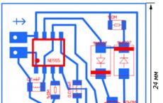
 As you can see, the scheme is simple. Main elements: current-limiting capacitor, rectifier diode bridge on four diodes, battery, switch, super-bright LEDs, LED indicating flashlight battery charging.

Well, now, in order, about the purpose of all the elements in the flashlight.
Current limiting capacitor. It is designed to limit the charging current of the battery. Its capacity may vary for each type of flashlight. A non-polar mica capacitor is used. The operating voltage must be at least 250 volts. In the circuit, it must be shunted, as shown, with a resistor. It serves to discharge the capacitor after you remove the flashlight from the charging socket. Otherwise, you could get an electric shock if you accidentally touch the 220 volt mains terminals of the flashlight. The resistance of this resistor must be at least 500 kΩ.

The rectifier bridge is assembled on silicon diodes with a reverse voltage of at least 300 volts.
A simple red or green LED is used to indicate that the flashlight battery is charging. It is connected in parallel with one of the rectifier bridge diodes. True, in the diagram, I forgot to indicate the resistor connected in series with this LED.
It makes no sense to talk about the rest of the elements, so everything should be clear anyway.
I would like to draw your attention to the main points of repairing an LED flashlight. Let's consider the main malfunctions and how to fix them.
1. The flashlight stopped shining. There are not so many options here. The reason may be the failure of superbright LEDs. This can happen for example in the following case. You put the flashlight on charge and accidentally turned on the switch. In this case, a sharp current surge will occur and one or more diodes of the rectifier bridge may be punctured. And behind them, the capacitor may not be able to withstand it and will close. The battery voltage will rise sharply and the LEDs will fail. So, in any case, do not turn on the flashlight when charging, if you do not want to throw it away.

2. Flashlight won't turn on. Well, here you need to check the switch.
3. The flashlight runs out very quickly. If your flashlight is "experienced", then most likely the battery has worked out its service life. If you actively use the flashlight, then after one year of operation the battery no longer holds.

Problem 1. LED flashlight does not turn on or flickers during operation
This is usually the reason for poor contact. The easiest treatment is to tighten all threads tightly. If the flashlight does not work at all, start by checking the battery. Perhaps it is discharged or out of order.

Unscrew the back cover of the lamp and use a screwdriver to close the housing with the negative contact of the battery. If the flashlight lights up, then the problem is in the module with the button.
90% of the buttons of all LED lights are made according to the same scheme: The button body is made of aluminum with a thread, a rubber cap is inserted there, then the button module itself and a pressure ring for contact with the body.

The problem is most often solved in a loosely clamped pressure ring. To eliminate this malfunction, it is enough to find round-nose pliers with thin stings or thin scissors that need to be inserted into the holes, as in the photo, and turned clockwise.
If the ring moves, then the problem has been fixed. If the ring is in place, then the problem lies in the contact of the button module with the body. Unscrew the retaining ring counterclockwise and pull the button module outward. Often poor contact occurs due to oxidation of the aluminum surface of the ring or the rim on the PCB. Indicated by arrows)
 It is enough to simply wipe these surfaces with alcohol and the functionality will be restored.
 Button modules are different. Some have contact through the PCB, others have contact through the side tabs to the body of the flashlight. Just bend such a tab to the side to make the contact tighter. Alternatively, you can solder tin, so that the surface is thicker and the contact is pressed better. All LED lights, in principle, are arranged the same
The plus goes through the positive contact of the battery to the center of the LED module, while the minus goes through the body and is closed with a button.
It will not be superfluous to check the tightness of the LED module inside the case. This is also a common problem with LED lights.

Using round nose pliers or pliers, rotate the module clockwise until it stops. Be careful, it is easy to damage the LED at this point.
These actions should be enough to restore the functionality of the LED flashlight.
It is worse when the flashlight works and the modes are switched, but the beam is very dim, or the flashlight does not work at all and there is a burning smell inside.

Problem 2. The flashlight works fine, but dimly, or does not work at all and there is a burning smell inside

Most likely, the driver is out of order. The driver is an electronic circuit on transistors that controls the flashlight modes and is also responsible for a constant voltage level regardless of battery discharge.
You need to unsolder the burned-out driver and solder a new driver, or connect the LED directly to the battery. In this case, you lose all modes and remain only with the maximum.
Sometimes (much less often) the LED fails, which can be checked very easily. bring the voltage 4.2 V / to the LED contact pads. The main thing is not to mix up the polarity. If the LED is on brightly, then the driver is out of order, if on the contrary, you need to order a new LED.
Unscrew the LED module from the case. There are different modules, but as a rule, they are made of copper or brass and
The weakest point of such lights is the button. Its contacts are oxidized, as a result of which the flashlight begins to shine dimly, and then it may stop turning on altogether. The first sign is that the flashlight with a normal battery shines weakly, but if you click the button several times, the brightness increases.
 The easiest way to make such a lantern shine is to do the following:
 1. Take a thin stranded wire, cut off one vein. 2. We wind the wiring on the spring. 3. We bend the wire so that the battery does not break it. The wire should protrude slightly over the curling part of the flashlight. 4. Twist tightly. We break off the excess wire (tear it off). As a result, the wire provides good contact with the negative part of the battery and the flashlight shines with the proper brightness. Of course, during such a repair, the button is not the lot, therefore, turning on - turning off the flashlight is done by turning the head part. My Chinese worked like that for a couple of months. If the battery needs to be replaced, do not touch the back of the lamp. We turn our head away.

Today I decided to bring the button back to life. The button is in a plastic case, which is simply pressed into the back of the flashlight. In principle, it can be pushed back, but I did it a little differently:
1. Make a pair of holes with a 2 mm drill bit to a depth of 2-3 mm. 2. Now you can unscrew the housing with the button with tweezers. 3. Extract the button 4. The button is assembled without glue and latches, so it is easy to disassemble it with a clerical knife. The photo shows that the movable contact has oxidized (round garbage in the center, similar to a button). It can be cleaned with an eraser or fine sandpaper and put the button back together, but I decided to additionally irradiate both this part and the fixed contacts.

1. We clean with a fine sandpaper. 2. We serve with a thin layer the places marked in red. We wipe the flux with alcohol, assemble the button. 3. For added reliability, I soldered the spring to the bottom pin of the button. 4. Putting everything back. After the repair, the button works fine. Of course, tin also oxidizes, but since tin is a fairly soft metal, I hope that the oxide film will break easily when the button is operated. It is not for nothing that the central contact on the bulbs is made of tin.

IMPROVING FOCUSING.
What is a "hotspot", my Chinese person was very vague, so I decided to enlighten him. Unscrew the head part.
1. There is a small hole in the board (arrow). With the help of an awl, we unscrew the filling, while lightly press the outside of the glass with your finger. This makes it easier to get out. 2. Remove the reflector. 3. We take ordinary office paper, punch 6-8 holes with an office punch. The diameter of the holes of the hole punch perfectly matches the diameter of the LED. Cut out 6-8 paper washers. 4. Put the washers on the LED and press down with the reflector, then you have to experiment with the number of washers. In this way, I improved focusing in a pair of flashlights, the number of washers was in the range of 4-6. On the current patient, it took 6.

The Chinese save on everything. A couple of extra details - an increase in the cost price, so they do not put it.
The main part of the diagram (marked in green) can be different. On one or two transistors or on a specialized microcircuit (I have a circuit of two parts: a choke and a microcircuit with 3 legs, similar to a transistor). But on the part marked in red - they save. I added a capacitor and a pair of 1n4148 diodes in parallel (I didn't find a Schottky). The brightness of the LED has increased by 10-15 percent.

remontavto-moto-velo.blogspot.com
Modification of the LED flashlight - RadioRadar
Lighting engineering
Home For radio amateurs Lighting engineering
In the dark, a pocket torch is an irreplaceable thing. However, the commercially available plug-in rechargeable battery samples are disappointing. For some time after the purchase, they still work, but then the lead-acid gel battery degrades and one charge starts to suffice for only a few tens of minutes of glow. And often during charging with the flashlight on, the LEDs burn out one after another. Of course, given the low price of a flashlight, you can buy a new one every time, but it is more expedient to understand the reasons for the failures once, eliminate them in the existing flashlight and forget about the problem for many years.

Consider in detail the one shown in Fig. 1 diagram of one of the failed lamps and determine its main disadvantages. To the left of the GB1 battery is the unit responsible for charging it. The charging current is set by the capacity of the capacitor C1. Resistor R1, installed in parallel with the capacitor, discharges it after disconnecting the flashlight from the network. The red LED HL1 is connected through a limiting resistor R2 in parallel to the lower left diode of the VD1-VD4 rectifier bridge in reverse polarity. The current flows through the LED during those half-periods of the mains voltage in which the upper left diode of the bridge is open. Thus, the glow of the HL1 LED only indicates that the flashlight is connected to the network, and not about the ongoing charging. It will glow even if the battery is missing or faulty.
The current consumed by the flashlight from the mains is limited by the capacitance of the capacitor C1 to approximately 60 mA. Since part of it branches off into the HL1 LED, the charging current for the GB1 batteries is about 50 mA. The XS1 and XS2 sockets are for measuring battery voltage.
Resistor R3 limits the battery discharge current through the parallel-connected EL1-EL5 LEDs, but its resistance is too low and a current exceeding the nominal current flows through the LEDs. The brightness of this increases slightly, and the rate of degradation of LED crystals increases markedly.
Now about the reasons for the burnout of LEDs. As you know, when charging an old lead-acid battery, the plates of which were sulfated, there is an additional voltage drop across its increased internal resistance. As a result, when charging is in progress, the voltage at the terminals of such a battery or their battery may be 1.5 ... 2 times higher than the nominal. If at this moment, without stopping charging, close switch SA1 to check the brightness of the LEDs, then the increased voltage will be sufficient to significantly exceed the permissible current through them. The LEDs will fail one by one. As a result, burned-out LEDs are added to the battery unusable for further operation. It is impossible to repair such a flashlight - there are no spare batteries on sale.

The proposed lantern modification scheme, shown in Fig. 2, allows you to eliminate the described disadvantages and exclude the possibility of failure of its elements in case of any erroneous actions. It consists in such a change in the scheme for connecting the LEDs to the battery so that its charging is interrupted automatically. This is achieved by replacing the SA1 switch with a switch. The limiting resistor R5 is selected so that the total current through the EL1-EL5 LEDs at a GB1 battery voltage of 4.2 V is 100 mA. Since the SA1 switch is a three-position switch, it became possible to implement an economical mode of reduced brightness of the flashlight by adding a resistor R4 to it.
The indicator on the HL1 LED has also been redesigned. Resistor R2 is connected in series with the battery. The voltage falling on it when the charging current flows is applied to the LED HL1 and the limiting resistor R3. Now it is the charging current flowing through the GB1 battery that is indicated, and not just the presence of the mains voltage.
The unusable gel battery is replaced with a three-Ni-Cd battery with a capacity of 600 mAh. The duration of its full charge is about 16 hours, and it is impossible to spoil the battery without stopping charging in time, since the charging current does not exceed a safe value, numerically equal to 0.1 of the nominal battery capacity.

Instead of the burned ones, HL-508h338WC LEDs with a diameter of 5 mm of white glow with a nominal brightness of 8 cd at a current of 20 mA (maximum current - 100 mA) and an angle of radiation of 15 ° are installed. In fig. 3 shows the experimental dependence of the voltage drop across such an LED on the current flowing through it. Its 5mA value corresponds to an almost completely discharged GB1 battery. Nevertheless, the brightness of the flashlight in this case remained sufficient.
The lantern, converted according to the considered scheme, has been successfully operating for several years. A noticeable decrease in the brightness of the glow occurs only when the battery is almost completely discharged. This just serves as a signal to charge it. As you know, fully discharging Ni-Cd batteries before charging increases their longevity.
Among the disadvantages of the considered modification method, it is possible to note the rather high cost of a battery of three Ni-Cd batteries and the complexity of its placement in the body of the lantern instead of the standard lead-acid one. The author had to cut the outer membrane of the new battery in order to more compactly accommodate the batteries that form it.
Therefore, when finalizing one more flashlight with four LEDs, it was decided to use only one Ni-Cd battery and a LED driver on a ZXLD381 microcircuit in a SOT23-3 package http://www.diodes.com/datasheets/ ZXLD381.pdf. With an input voltage of 0.9 ... 2.2 V, it provides LEDs with a current of up to 70 mA.

In fig. 4 shows the power supply circuit for HL1-HL4 LEDs using this microcircuit. The graph of the typical dependence of their total current on the inductance of the inductor L1 is shown in Fig. 5. With its inductance of 2.2 μH (a DLJ4018-2.2 choke is used), each of the four parallel-connected EL1-EL4 LEDs has 69/4 \u003d 17.25 mA of current, which is quite enough for their bright glow.

Of the other attachments, only a Schottky diode VD1 and a capacitor C1 are required for the microcircuit to operate in a smoothed output current mode. It is interesting that on the typical diagram of the application of the ZXLD381 microcircuit, the capacity of this capacitor is 1 F. The battery charging unit G1 is the same as in Fig. 2. The limiting resistors R4 and R5 available in the same place are no longer needed, and two positions are sufficient for the SA1 switch.
Due to the small number of parts, the lantern was reworked by a hinged mounting. The G1 battery (Ni-Cd, AA size, 600 mAh) is installed in the corresponding holder. In comparison with the lantern modified according to the diagram in fig. 2, the brightness turned out subjectively somewhat lower, but quite sufficient.
Date of publication: 31.05.2013
Readers' opinions
No comments yet. Your comment will be the first.
You can leave your comment, opinion or question on the above material:
www.radioradar.net
 One of these days a neighbor comes to us and brings with him a nice portable lantern.
  The flashlight worked for six months, lay idle for six months, now it is needed, but does not work. The flashlight was used in the basement; the light is only above the door, and the distant shelves with jam - pickles are gloomy. The lantern lived in the basement, hung on the jamb under the switch and the socket. The basement is dry, the husband wanted to make a carrying with a light bulb, but a lantern appeared - there was no need for it. While the women were chatting among themselves, I took up the lantern. The lantern was made by the Chinese, there is a helium acid battery,
  incandescent halogen lamp,
  battery charger,
  assembled according to a primitive scheme.
Made the necessary measurements of the battery with a multimeter:
 Voltage and current are at zero, resistance is infinity. There is no point in fiddling with such a battery, I had the opportunity to try to reanimate with such, but if she died, she died. It was decided to make a simple flashlight with an LED, powered from a 220 volt network.
  A neighbor brought in a power cord of about five meters with a plug at one end.
  There was a 12 volt LED light bulb,
  a workable board from the required charger was also available,
  installed only a Zener diode D815D instead of the indicator LED,
  Yes, the power cord was soldered to the board.
  Plugged the plug into the network and the gentle light of the lantern illuminated the room.
  Delov was only worth a ruble and a half, and he received a three-liter jar of pickled vegetables as a present from a neighbor.
usamodelkina.ru
LED torch from 1.5 V and below
Blocking - the generator is a generator of short-term impulses repetitive at rather long intervals.
One of the advantages of blocking generators is their relative simplicity, the ability to connect the load through a transformer, high efficiency, and connect a sufficiently powerful load.
Block generators are very often used in amateur radio circuits. But we will run an LED from this generator.
Very often on a hike, fishing or hunting, you need a flashlight. But not always there is a rechargeable battery or 3V batteries at hand. This circuit can run the LED at full power from a nearly discharged battery.
A little about the scheme. Details: any transistor (n-p-n or p-n-p) can be used in my KT315G circuit.
The resistor needs to be selected, but more on that later.
The ferrite ring is not very large.
And the diode is high frequency with low voltage drop.
So, I was cleaning up a drawer in the table and found an old flashlight with an incandescent light bulb, of course, burned out, and recently I saw a diagram of this generator.
And I decided to solder the circuit and put it in a flashlight.
Well, let's get started:
First, let's put it together according to this scheme.
We take a ferrite ring (I pulled out a fluorescent lamp from the ballast) and wind 10 turns with a wire of 0.5-0.3 mm (it can be thinner, but it will not be convenient). We wound it, make a loop, well, or a bend, and wind another 10 turns.
Now we take the KT315 transistor, the LED and our transformer. We collect according to the scheme (see above). I also put a capacitor in parallel with the diode, so it shone brighter.
So they collected it. If the LED is off, reverse the polarity of the battery. Still off, check if the LED and transistor are connected correctly. If everything is correct and still does not burn, then the transformer is not wound correctly. To be honest, my scheme also started up far from the first time.
Now we supplement the diagram with the rest of the details.
Putting the diode VD1 and the capacitor C1, the LED will light up brighter.
The last step is the selection of the resistor. Instead of a constant resistor, we put a variable one at 1.5 kOhm. And we begin to twist. You need to find the place where the LED shines brighter, while you need to find a place where if you increase the resistance even slightly, the LED goes out. In my case, it is 471 Ohm.
Okay, now more to the point))
We disassemble the flashlight
Cut out a circle from one-sided thin fiberglass to the size of the flashlight tube.
Now we go and look for details of the required denominations in the size of a few millimeters. KT315 transistor
Now we mark the board and cut the foil with a clerical knife.
We trick the fee
We fix the jambs, if any.
Now, to solder the board, we need a special tip, if not, it doesn't matter. We take a wire 1-1.5 mm thick. We clean it thoroughly.
Now we wind on the existing soldering iron. The end of the wire can be sharpened and tinned.
Well, let's start soldering the details.
You can use a magnifying glass.
Well, everything seems to be soldered, except for the capacitor, LED and transformer.
Now test run. We attach all these details (without soldering) to the "snot"
Hurrah!! Happened. Now you can solder all the details without fear.
I suddenly wondered what the output voltage was, I measured
3.7V is normal for a high power LED.
The most important thing is to solder the LED))
We insert into our flashlight, when I inserted, I soldered off the LED - it interfered.
And so, put in, made sure that everything crawls freely. Now we take out the board and cover the edges with varnish. That there was no short circuit, because the body of the flashlight is a minus.
Now we solder the LED back and check it again.
We checked it, everything works !!!
Now we carefully insert all this into the flashlight and turn it on.
Such a flashlight can be started even from a discharged battery, and if there are no batteries at all (for example, hunting in the forest). There are many different ways to get a small voltage (insert 2 wires of different metals into the potato) and start the LED.
Good luck!!!
sdelaysam-svoimirukami.ru
BATTERY LED
It was evening, there was nothing. And I started cleaning up my deposits of radio components and other electronic stuff accumulated in the area of \u200b\u200bthe table. Some in the barn, and some in the sofa. And I came across a simple burnt-out LED flashlight with a battery charged from a built-in transformerless rectifier in the process of putting things in order.
Since the LEDs themselves turned out to be alive, and the case seemed to be nothing, I decided to bring it to working condition. Of course, not according to the original Chinese scheme, but on a more perfect one. As planned, the updated rechargeable LED flashlight will be charged from the mains and shine for up to 20 hours from a lithium ionic (at a current of 50mA).

Do not be afraid - you do not need to solder expensive parts :) For these purposes, a ready-made charger from any mobile phone (lost a month ago) and also any mobile lithium-ion battery (they gave a phone drowned in the sea for spare parts) are perfect for these purposes.

What needs to be done? Just connect the charger to the battery, and it, in turn, to the LEDs.

Since there was a small square hole in the flashlight for an additional LED, I closed it with a piece of dark plexiglass, placing a red LED under it indicating that it was connected to the network for recharging. The LED turns on in parallel with the charger outputs.

The native plug of the lantern was lost, so I had to make a new one, having previously sawed it off from the above charger, from which the scarf was removed.

As you can see, there is enough space in the case for both the charger and other components of the LED flashlight.

When installing, please note that if the battery is directly soldered to the charging, then in the disconnected state there will be a small self-discharge of several milliamps. The way out is simple - put a diode of type IN4001 or similar for a current of more than 0.5A by plus.

Now when you turn on the flashlight with the toggle switch, the plus of the battery goes through a 20 Ohm resistor to the LEDs. And again pressing the toggle switch and throwing the plus on the battery - we transfer the flashlight to the mode of charging from the mains.

Despite the fact that the battery itself has a charge controller, I do not recommend leaving the flashlight plugged into the outlet for more than 5 hours. You never know ...


The finished LED rechargeable flashlight turned out to be very nice and easy to use. It shines quite enough for most purposes. Who needs extra power - look at powerful LEDs.


Here, using this simple design as an example, I showed the very principle of altering lanterns using the remains of non-working mobile phones, which I am sure you have accumulated a considerable amount.
LED Flashlights Forum
Discuss the article BATTERY LED
radioskot.ru
We are restoring and bringing to mind a Chinese flashlight. / Workshop / Not Waste
Many have a variety of Chinese flashlights that run on the same battery. Like this: Unfortunately, they are very short-lived. How to bring the flashlight back to life and some simple improvements that can improve such flashlights - I'll tell you further. The weakest point of such lights is the button. Her contacts are oxidized, as a result of which the flashlight begins to shine dimly, and then it may stop turning on altogether. The first sign is that a flashlight with a normal battery shines weakly, but if you click the button several times, the brightness increases. The easiest way to make such a lantern shine is to do the following: 1. Take a thin stranded wire, cut off one vein. 2. We wind the wiring on the spring. 3. Bend the wire so that the battery does not break it. The wire should protrude slightly above the curled part of the flashlight. 4. Tighten tightly. We break off the excess wire (tear off). As a result, the wire provides good contact with the negative part of the battery and the flashlight will shine with proper brightness. Of course, in such a repair, the button remains irrelevant, so turning on and off the flashlight is done by turning the head part. My Chinese man worked like this for a couple of months. If you need to change the battery, do not touch the back of the flashlight. We turn our head away.RESTORING THE PERFORMANCE OF THE BUTTON.
Today I decided to bring the button back to life. The button is in a plastic case, which is simply pressed into the back of the flashlight. In principle, it can be pushed back, but I did it a little differently: 1. Make a pair of holes with a 2 mm drill bit to a depth of 2-3 mm. 2. Now you can unscrew the housing with the button with tweezers. 3. Extract the button 4. The button is assembled without glue and latches, so it is easy to disassemble it with a clerical knife. The photo shows that the movable contact has oxidized (round garbage in the center, similar to a button). It can be cleaned with an eraser or fine sandpaper and put the button back together, but I decided to additionally irradiate both this part and the fixed contacts. 1. We clean it with fine sandpaper. 2. We serve with a thin layer the places marked in red. We wipe the flux with alcohol, assemble the button. 3. For added reliability, I soldered the spring to the bottom pin of the button. 4. Putting everything back. After the repair, the button works fine. Of course, tin also oxidizes, but since tin is a fairly soft metal, I hope that the oxide film will break easily when the button is operated. It is not for nothing that the central contact on the bulbs is made of tin.
IMPROVING FOCUSING.
What is a "hotspot", my Chinese had a very vague idea, so I decided to enlighten him. Unscrew the head. 1. There is a small hole in the board (arrow). With the help of an awl, we unscrew the filling, while lightly press the outside of the glass with your finger. This makes it easier to get out. 2. Remove the reflector. 3. We take ordinary office paper, punch 6-8 holes with an office punch. The diameter of the holes of the hole punch perfectly matches the diameter of the LED. Cut out 6-8 paper washers. 4. Put the washers on the LED and press down with the reflector, then you have to experiment with the number of washers. In this way, I improved focusing in a pair of flashlights, the number of washers was in the range of 4-6. On the current patient it took 6 of them, which turned out in the end: On the left - our Chinese, on the right - Fenix \u200b\u200bLD 10 (at the minimum). The result is quite pleasant. The hot spot has become pronounced and even.
INCREASE BRIGHTNESS (for those who know a little about electronics).
The Chinese save on everything. A couple of extra details - an increase in the cost price, so they do not put it. The main part of the diagram (marked in green) can be different. On one or two transistors or on a specialized microcircuit (I have a circuit of two parts: a choke and a microcircuit with 3 legs, similar to a transistor). But on the part marked in red - they save. I added a capacitor and a pair of 1n4148 diodes in parallel (I didn't find a Schottky). The brightness of the LED has increased by 10-15 percent.
1. This is how the LED looks like in similar Chinese. From the side you can see that there are thick and thin legs inside. A thin leg is a plus. You need to navigate by this sign, because the colors of the wires can be completely unpredictable. 2. This is how the board looks like, to which the LED is soldered (on the back side). Foil is marked in green. The wires from the driver are soldered to the LED legs. 3. Use a sharp knife or a triangular file to cut the foil on the plus side of the LED and sand the entire board to remove the varnish. 4. We solder diodes and a capacitor. I took the diodes from a broken computer power supply, the tantalum capacitor dropped out of some burned-out hard drive. The plus wire now needs to be soldered to the pad with the diodes.
As a result, the flashlight produces (by eye) 10-12 lumens (see photo with hotspots), judging by the phoenix, which produces 9 lumens in the minimum mode.
And the last thing: the advantage of the Chinese over the branded flashlight (yes, don't laugh) Branded flashlights are designed to use rechargeable batteries, so my Fenix \u200b\u200bLD 10 simply won't turn on with a battery discharged to 1 volt. I took a dead alkaline battery, which had worked out its life in a computer mouse. The multimeter showed that she sat down to 1.12v. The mouse did not work on it, Fenix, as I said, did not start. But the Chinese man works! Left - Chinese, right - Fenix \u200b\u200bLD 10 at minimum (9 lumens). Unfortunately, the white balance is out of order. The phoenix has a temperature of 4200K. The Chinese man is blue, but not as bad as in the photo. For the sake of interest, I tried to finish off the battery. At this brightness level (5-6 lumens per eye), the flashlight worked for about 3 hours. Brightness is enough to illuminate under your feet in a dark entrance / forest / basement. Then for another 2 hours, the brightness decreased to the level of the "firefly". Agree, 3-4 hours with acceptable light can solve a lot. For this, let me take my leave. Star4ok.

Hh004F wiring diagram
Light sensor connection diagram for lighting
Click Class
Tell VK
An electric flashlight refers, as it were, to an additional auxiliary tool for carrying out any work in the presence of poor lighting or no lighting at all. Each of us chooses the type of flashlight at our discretion:
- head Torch;
- pocket flashlight;
- hand-held flashlight
Simple flashlight circuit

The electrical diagram of a simple flashlight \\ Fig. 1 \\ consists of:
- battery cells;
- light bulbs;
- key \\ switch \\.
The scheme in its execution is simple and does not require explanations in this regard. The reasons for the malfunction of the flashlight with this scheme can be:
- oxidation of contact connections with batteries;
- oxidation of the contacts of the bulb holder;
- oxidation of the contacts of the bulb itself;
- malfunction of the key \\ light switch \\;
- malfunction of the light bulb itself \\ burned out light bulb \\;
- lack of contact connection with the wire;
- lack of battery power.
Other reasons for the malfunction may be any mechanical damage to the body of the flashlight.
Diagram of a rechargeable LED flashlight

headlamp with LED BL - 050 - 7C
The BL - 050 - 7C flashlight comes on sale with a built-in charger; when such a flashlight is connected to an external AC voltage source, the battery is recharged.
Rechargeable batteries, or rather electrochemical accumulators, - the principle of charging such cells is based on the use of reversible electrochemical systems. Substances formed during the discharge of the battery, under the influence of electric current, are able to restore their original state. That is, we recharged the flashlight and can continue to use it. Such electrochemical batteries or individual cells can consist of a certain amount, depending on the voltage consumed:
- the number of bulbs;
- type of bulbs.
The number, the set of such individual elements of the flashlight, is a battery.
The electric circuit of the flashlight \\ Fig. 2 \\ can be considered both consisting of a simple incandescent light bulb and a certain number of LED bulbs. For any flashlight circuit, what exactly is important? - It is important that the energy consumed by the light bulbs in the electrical circuit corresponds to the output voltage of the power source \\ battery, consisting of separate elements \\.
We read the connection diagram:
Resistor R1 with a resistance of 510 kOhm and a rated power of 0.25 W in the electrical circuit is connected in parallel, due to this large resistance, the voltage in the further section of the electrical circuit is significantly lost, or rather, part of the electrical energy is converted into heat energy.
With a resistor R2 \\ with a resistance of 300 ohms and a rated power of 1 W \\ the current is supplied to the VD2 LED. This LED serves as an indicator light to indicate the connection of the flashlight charger to an external AC voltage source.
The anode of the diode VD1 is supplied with current from the capacitor C1. The capacitor in the electrical circuit is a smoothing filter, part of the electrical energy is lost with a positive half-cycle of the sinusoidal voltage, since during this half-cycle the capacitor is charged.
With a negative half-cycle, the capacitor is discharged and the current flows to the anode of the cathode VD1. An external voltage drop for a given electrical circuit occurs when there are two resistors and a light bulb in the electrical circuit. Also, it can be taken into account that when the current passes from the anode to the cathode - in the VD1 diode - there is also its own potential barrier. That is, the diode also tends to be heated to some extent, at which an external voltage drop occurs.
On the GB1 battery, consisting of three cells, a current of two potentials \\ + - \\ is supplied from the charger \\ when the flashlight is connected to an external source of alternating voltage \\. In the battery, the electrochemical composition of the battery is restored to its original state.
The following circuit \\ Fig. 3 \\ which is found in LED flashlights, consists of the following electronic elements:

- two resistors \\ R1; R2 \\;
- diode bridge consisting of four diodes;
- capacitor;
- diode;
- lED;
- key;
- batteries;
- light bulbs.
For a given circuit, the external voltage drop occurs due to all the constituent elements of the electronics - connected in this circuit. One diagonal of the diode bridge of the bridge circuit is connected to an external AC voltage source, the other diagonal of the diode bridge is connected to the load - consisting of a certain number of light-emitting diodes.
All detailed descriptions on replacing electronics elements during the repair of a flashlight, as well as diagnostics of these elements - you can find on this site, which contains similar topics in which repair of household appliances is seen.
How to repair an LED flashlight
For my work, I sometimes have to use a headlamp. Approximately six months after the purchase, the flashlight's rechargeable battery stopped charging after it was turned on for recharging via the power cord.
When establishing the cause of the headlamp breakdown, the repair was accompanied by photographs in order to present this topic in an illustrative example.
The cause of the malfunction was not clear at the beginning, since when the flashlight was turned on for recharging, the signal light came on, and the flashlight itself, when the switch button was pressed, emitted a weak light. So what could be the reason for such a malfunction? Is the battery malfunctioning or some other reason?
It was necessary to open the body of the flashlight to examine it. On the photographs \\ photo No. 1 \\ with the tip of a screwdriver, the places of fastening \\ connection \\ case are indicated.
If the body of the flashlight cannot be opened, you need to carefully examine whether all the screws have been removed.
Photo # 2 shows a buck converter in both voltage and current.
You should not look for the cause of the malfunction in the circuit, since when connected to an external source, the signal light is on \\ photo No. 2 red LED light \\. We check further connections.
In front of us on the photograph \\ photo # 3 \\ shows the light switch of an LED flashlight. The contacts of the push-button post of the switch are a double light switch device, where for this example light up:
- six LED lamps,
- twelve LED bulbs
flashlight. Two contacts of the switch, as we can see, are short-circuited and a common wire is soldered to these contacts. Two wires are soldered to the next two contacts of the switch - separately, from which the current flows to the lighting:
- six lamps;
- twelve lamps.


The contacts of the light switch \\ when switching \\ it is enough to check with a probe as shown in photo №4. We touch the common contact \\ two short-circuited contacts \\ with a finger and alternately touch the other two contacts with a probe.

If the switch is working properly, the LED lamp of the probe lights up \\ photo # 4 \\. The light switch is operational, we carry out further diagnostics.
The power cord can also be checked here with a probe \\ photo # 5 \\. To do this, with your finger, you need to short-circuit the pins of the plug and alternately connect the probe to the first and second contacts of the cable connector. If the probe light comes on, there is no break in the power cord.


The power cord for recharging the battery is working properly, we carry out further diagnostics. You should also check the flashlight battery.

The enlarged image of the battery \\ photo # 6 \\ shows that a constant voltage of 4 volts is supplied to recharge it. The current strength of this voltage is 0.9 ampere / hour. We check the battery.

The multimeter in this example is set to a DC voltage measurement range of 2 to 20 Volts so that the measured voltage matches the specified range.

As we can see, the display of the device shows a constant battery voltage of 4.3 Volts. In fact, this indicator should take on a greater value - that is, there is insufficient voltage to power the LED lamps. LED lamps take into account potential barrier for each such lamp - as we know from electrical engineering. Consequently, the battery does not receive the required voltage when recharging.

And here is the whole reason for the malfunction \\ photo # 8 \\. This cause of the malfunction was not immediately established - in the rupture of the contact connection of the wire with the battery.
What can be noted here:
The wires in this circuit are unreliable for soldering, since the thin section of the wire does not allow them to be securely attached at the soldering point.
But even this reason for the breakdown is removable, the wiring was replaced with a more reliable section and the LED flashlight is currently operational, it works flawlessly.
I consider the stated topic unfinished, will be given in examples for you - repairs of other types of flashlights.
That's all for now.
Tweet
Tell VK
Click Class
I would call it "Notes of a Shitty Electrician"! The author simply does not understand how the circuit works, its elements, he confuses concepts. Using the example of the circuit in Fig. 2: R1 serves to discharge capacitor C1 after disconnecting the flashlight from the mains for safety reasons. There is no "loss" of voltage "in the further section", let the Author connect a voltmeter and look at it to make sure of this. Resistor R2 serves as a current limiter. The VD2 LED serves not only as an indicator, but also supplies a positive potential to the + battery.
Capacitor C1 in this circuit is a damping (and not a smoothing filter), so it is on it that the excess of AC voltage is damped.
About the potential barrier also heaped up this - it's funny to read. And the current "current of two potentials" ?! According to classical physics, current flows from a positive potential to a negative one, while electrons move in reverse.
Did the author go to school?
And he has this everywhere. It's sad. But someone takes his "revelations" at face value.
Hello povaga! I stopped charging the "Oblic 2077" flashlight on one LED. I can’t find any schemes, but it’s like in figure # 3. Difference: there is no capacitor C2, diode VD5, two resistors and a three-pin board are soldered to the SA1 switch. I measured the voltage after the bridge - 2 volts, the battery is 4 volts, how can it be charged? Please help with the operation diagram and electrical circuit. Thanks in advance, Regards, Doldin.
For safety and the ability to continue active activity in the dark, a person needs artificial lighting. Primitive people pushed the darkness apart, setting fire to tree branches, then invented a torch and a kerosene stove. And only after the invention of the prototype of the modern battery by the French inventor George Leclanche in 1866, and in 1879 by Thomson Edison of the incandescent lamp, did David Meisel have the opportunity to patent the first electric lantern in 1896.
Since then, nothing has changed in the electrical circuit of new lantern samples, until in 1923 the Russian scientist Oleg Vladimirovich Losev found a connection between luminescence in silicon carbide and a pn-junction, and in 1990, scientists failed to create an LED with a higher light output, allowing to replace a light bulb incandescent. The use of LEDs instead of incandescent lamps, due to the low power consumption of LEDs, made it possible to significantly increase the operating time of flashlights with the same capacity of batteries and accumulators, increase the reliability of flashlights and practically remove all restrictions on their area of \u200b\u200buse.
The LED rechargeable flashlight that you see in the photo came to me for repair with a complaint that the Lentel GL01 Chinese flashlight bought the other day for $ 3 does not shine, although the battery charge indicator is on.
External inspection of the lantern made a positive impression. High-quality casting of the case, comfortable handle and switch. The battery charging plugs are retractable, eliminating the need to store the power cord.
Attention! Care should be taken when disassembling and repairing the flashlight if it is connected to the mains. Touching exposed circuitry while connected to the mains may result in electric shock.
How to disassemble the Lentel GL01 LED rechargeable torch
Although the flashlight was subject to warranty repair, remembering my walks during the warranty repair of a failed electric kettle (the kettle was expensive and the heating element burned out in it, so it was not possible to repair it with my own hands), I decided to do the repair myself.
It turned out to be easy to disassemble the lantern. It is enough to turn the ring securing the protective glass by a small angle counterclockwise and pull it off, then unscrew several screws. It turned out that the ring is fixed to the body using a bayonet connection.
After removing one of the halves of the body of the flashlight, access to all its nodes appeared. On the left of the photo, a printed circuit board with LEDs is visible, to which a reflector (light reflector) is attached using three self-tapping screws. In the center there is a black battery with unknown parameters, there is only a marking of the polarity of the terminals. To the right of the battery is the printed circuit board for the charger and display. On the right is a power plug with retractable rods.
Upon closer examination of the LEDs, it turned out that there were black spots or dots on the emitting surfaces of the crystals of all LEDs. It became clear even without checking the LEDs with a multimeter that the flashlight does not shine due to their burnout.
There were also blackened areas on the crystals of two LEDs installed as a backlight on the battery charging indication board. In LED lamps and strips, one LED usually fails, and working as a fuse, protects the rest from burnout. And in the lantern, all nine LEDs went out of order at the same time. The battery voltage could not increase to a value that could damage the LEDs. To find out the reason, I had to draw an electrical schematic diagram.
Finding the cause of the flashlight failure
The electric circuit of the lantern consists of two functionally complete parts. The part of the circuit located to the left of the SA1 switch serves as a charger. And the part of the circuit shown to the right of the switch provides a glow.
The charger works as follows. The voltage from the 220 V household network is supplied to the current-limiting capacitor C1, then to the bridge rectifier assembled on VD1-VD4 diodes. From the rectifier, voltage is applied to the battery terminals. Resistor R1 serves to discharge the capacitor after removing the flashlight plug from the network. Thus, an electric shock from the discharge of the capacitor is excluded in the event of accidental hand touching of two pins of the plug at the same time.
The HL1 LED, connected in series with the current-limiting resistor R2 in the opposite direction with the upper right diode of the bridge, as it turned out, always lights up when the plug is inserted into the network, even if the battery is faulty or disconnected from the circuit.
The SA1 operating mode switch is used to connect individual groups of LEDs to the battery. As you can see from the diagram, it turns out that if the flashlight is connected to the mains for charging and the switch slider is in position 3 or 4, then the voltage from the battery charger also goes to the LEDs.
If a person turned on the flashlight and found that it was not working, and, not knowing that the switch engine must be set to the "off" position, which is not said in the operating instructions for the flashlight, connect the flashlight to the mains for charging, then at the expense voltage surge at the output of the charger, a voltage significantly higher than the calculated one will hit the LEDs. The current will flow through the LEDs in excess of the permissible current and they will burn out. With the aging of the acid battery due to the sulfation of the lead plates, the battery charge voltage increases, which also leads to burnout of the LEDs.
Another circuit solution that surprised me was the parallel connection of seven LEDs, which is unacceptable, since the current-voltage characteristics of even LEDs of the same type are different and therefore the current passing through the LEDs will also not be the same. For this reason, when choosing the value of the resistor R4 based on the maximum allowable current flowing through the LEDs, one of them may overload and fail, and this will lead to an overcurrent of the parallel connected LEDs, and they will also burn out.
Alteration (modernization) of the electric circuit of the lantern
It became obvious that the breakdown of the lantern was due to mistakes made by the developers of its electrical circuit diagram. To repair the flashlight and exclude its repeated breakdown, it is necessary to redo it by replacing the LEDs and making minor changes to the electrical circuit.
In order for the battery charge indicator to really signal its charging, it is necessary to turn on the HL1 LED in series with the battery. The LED needs a current of several milliamps to light up, and the current output from the charger should be about 100 mA.
To ensure these conditions, it is enough to disconnect the HL1-R2 chain from the circuit in the places indicated by the red crosses and install an additional 47 Ohm resistor Rd in parallel with it with a power of at least 0.5 W. The charge current flowing through Rd will create a voltage drop of about 3 V across it, which will provide the necessary current for the HL1 indicator to glow. At the same time, the connection point HL1 and Rd must be connected to pin 1 of switch SA1. In this simple way, the possibility of supplying voltage from the charger to the EL1-EL10 LEDs during battery charging will be excluded.
To equalize the magnitude of the currents flowing through the EL3-EL10 LEDs, it is necessary to exclude the resistor R4 from the circuit and in series with each LED connect a separate resistor with a nominal value of 47-56 Ohm.
Electrical diagram after revision
Minor changes made to the circuit have increased the information content of the charge indicator of an inexpensive Chinese LED flashlight and increased its reliability many times over. I hope that the manufacturers of LED lights, after reading this article, will make changes to the wiring diagrams of their products.
After the modernization, the electrical circuit diagram took the form as in the drawing above. If you need to illuminate with a flashlight for a long time and you do not need a high brightness of its glow, then you can additionally install a current-limiting resistor R5, due to which the operating time of the flashlight without recharging will double.
Repair of LED rechargeable flashlight
After disassembly, first of all, you need to restore the working capacity of the flashlight, and only then do the modernization.
Checking the LEDs with a multimeter confirmed their malfunction. Therefore, all the LEDs had to be evaporated and the holes for installing new diodes had to be freed from the solder.
Judging by their appearance, the board had lamp LEDs from the HL-508H series with a diameter of 5 mm. There were HK5H4U type LEDs from a linear LED lamp with similar technical characteristics. They came in handy for repairing the lantern. When soldering the LEDs to the board, you must remember to observe the polarity, the anode must be connected to the positive terminal of the battery or battery.
After replacing the LEDs, the PCB was connected to the circuit. The brightness of some LEDs was slightly different from others due to the common current-limiting resistor. To eliminate this disadvantage, it is necessary to remove the resistor R4 and replace it with seven resistors, connecting it in series with each LED.
To select the resistor that provides the optimal mode of operation of the LED, the dependence of the current flowing through the LED on the value of the series-connected resistance at a voltage of 3.6 V, equal to the voltage of the flashlight battery, was measured.
Based on the conditions for using the flashlight (in the event of power outages in the apartment), high brightness and illumination range were not required, so the resistor was chosen with a nominal value of 56 ohms. With such a current-limiting resistor, the LED will operate in light mode, and power consumption will be economical. If you want to squeeze out the maximum brightness from the flashlight, then you should use a resistor, as can be seen from the table, with a nominal value of 33 Ohm and make two modes of operation of the flashlight, including another common current-limiting resistor (in the diagram R5) with a nominal value of 5.6 Ohm.
To connect a resistor in series with each LED, you must first prepare the printed circuit board. To do this, you need to cut on it one by one any current-carrying track suitable for each LED and make additional contact pads. The current-carrying paths on the board are protected with a layer of varnish, which must be scraped off with a knife blade to copper, as in the photo. Then, tin the bare contact pads with solder.
It is better and more convenient to prepare a printed circuit board for mounting resistors and solder them if the board is fixed on a standard reflector. In this case, the surface of the LED lenses will not be scratched, and it will be more convenient to work.
Connecting the diode board after repair and modernization to the flashlight battery showed sufficient for illumination and the same brightness of all LEDs.
I didn't have time to repair the previous flashlight, when the second one got into repair, with the same malfunction. I did not find information about the manufacturer and technical characteristics on the body of the flashlight, but judging by the handwriting of the manufacture and the reason for the breakdown, the manufacturer is the same, the Chinese Lentel.
By the date on the body of the flashlight and on the battery, it was possible to establish that the flashlight was already four years old and, according to its owner, the flashlight worked flawlessly. Obviously, the flashlight lasted a long time thanks to the warning sign "Do not turn on while charging!" on a hinged lid covering the compartment, which contains a plug for connecting the flashlight to the mains to charge the battery.
In this model of the flashlight, the LEDs are included in the circuit according to the rules, a 33 Ohm resistor is installed in series with each. The size of the resistor is easy to find by color coding using an online calculator. Checking with a multimeter showed that all the LEDs are faulty, the resistors were also open-circuit.
Analysis of the reasons for the failure of the LEDs showed that due to the sulfation of the plates of the acid battery, its internal resistance increased and, as a result, its charging voltage increased several times. During charging, the flashlight was turned on, the current through the LEDs and resistors exceeded the limit, which led to their failure. I had to replace not only the LEDs, but all the resistors. Based on the above specified operating conditions of the flashlight, 47 Ohm resistors were selected for replacement. The resistor value for any type of LED can be calculated using an online calculator.
Alteration of the battery charging mode indication circuit
The lamp has been repaired, and you can start making changes to the battery charging indication circuit. For this, it is necessary to cut the track on the printed circuit board of the charger and display in such a way that the HL1-R2 chain from the side of the LED is disconnected from the circuit.
The lead-acid AGM battery was brought to a deep discharge, and an attempt to charge it with a standard charger was unsuccessful. I had to charge the battery using a stationary power supply with the function of limiting the load current. The battery was supplied with a voltage of 30 V, while at the first moment of time it consumed a current of only a few mA. Over time, the current began to increase and after a few hours it increased to 100 mA. After fully charged, the battery was installed in the flashlight.
Charging deeply discharged lead-acid AGM batteries after long-term storage with increased voltage allows them to restore their performance. I have tested the method on AGM batteries more than a dozen times. New batteries that do not want to be charged with standard chargers, when charged from a constant source at a voltage of 30 V, are restored to almost their original capacity.
The battery was discharged several times by turning on the flashlight in operating mode and charged using a standard charger. The measured charge current was 123 mA, with a voltage at the battery terminals of 6.9 V. Unfortunately, the battery was worn out and it was enough for the flashlight to work for 2 hours. That is, the capacity of the battery was about 0.2 A × hour, and for a long-term operation of the flashlight it needs to be replaced.
The HL1-R2 chain on the PCB was well placed, and it was necessary to cut just one conductor at an angle, as in the photo. The cutting width must be at least 1 mm. Calculation of the resistor rating and testing in practice showed that for the stable operation of the battery charging indicator, a 47 Ohm resistor with a power of at least 0.5 W. is required.
The photo shows a printed circuit board with a soldered current limiting resistor. After this modification, the battery charge indicator only lights up if the battery is actually being charged.
Modernization of the mode switch
To complete the repair and modernization of the lanterns, it is necessary to re-solder the wires at the switch terminals.
In the models of repaired lamps, a four-position slide-type switch is used to turn on. The average conclusion in the above photograph is general. When the switch slider is in the extreme left position, the common terminal is connected to the left terminal of the switch. When you move the switch slider from the extreme left position one position to the right, its general output is connected to the second output and with further movement of the slider sequentially to 4 and 5 outputs.
To the middle common terminal (see photo above), you need to solder the wire coming from the positive terminal of the battery. Thus, it will be possible to connect the battery to a charger or LEDs. You can solder a wire from the main board with LEDs to the first terminal, and a 5.6 Ohm current-limiting resistor R5 can be soldered to the second to enable the flashlight to switch to an energy-saving mode. Solder the lead from the charger to the rightmost terminal. This will exclude the possibility of turning on the flashlight while the battery is charging.
Repair and modernization
LED rechargeable flashlight "Foton PB-0303"
Another example from a series of Chinese-made LED lanterns, called Photon PB-0303 LED floodlight, came into my repair. The flashlight did not react when the power button was pressed, an attempt to charge the flashlight battery using a charger was unsuccessful.
The flashlight is powerful, expensive, costs about $ 20. According to the manufacturer, the luminous flux of the flashlight reaches 200 meters, the body is made of shock-resistant ABS plastic, the kit includes a separate charger and a shoulder strap.
Photon LED flashlight has good maintainability. To gain access to the electrical circuit, simply unscrew the plastic ring that holds the protective glass by rotating the ring counterclockwise while looking at the LEDs.
When repairing any electrical appliance, troubleshooting always begins with the power source. Therefore, the first thing was measured with a multimeter turned on in the mode, the voltage at the terminals of the acid battery. It was 2.3 V, instead of 4.4 V required. The battery has been completely discharged.
When the charger was connected, the voltage at the battery terminals did not change, it became obvious that the charger was not working. The flashlight was used until the battery was completely discharged, and then it was not used for a long time, which led to a deep discharge of the battery.
It remains to check the health of the LEDs and other elements. For this, the reflector was removed, for which six screws were unscrewed. On the printed circuit board there were only three LEDs, a chip (microcircuit) in the form of a droplet, a transistor and a diode.
From the board and the battery, five wires went into the handle. In order to understand their connection, it was necessary to disassemble it. To do this, use a Phillips screwdriver to unscrew the two screws inside the flashlight, which were located next to the hole into which the wires went.
To detach the handle of the flashlight from its body, it must be moved away from the fastening screws. This must be done carefully so as not to tear off the wires from the board.
As it turned out, there were no electronic elements in the pen. Two white wires were soldered to the terminals of the on / off button of the flashlight, and the rest to the connector for connecting the charger. A red wire was soldered to pin 1 of the connector (conditional numbering), which was soldered with the second end to the positive input of the printed circuit board. A blue and white conductor was soldered to the second contact, which was soldered to the negative side of the printed circuit board with the second end. A green wire was soldered to pin 3, the other end of which was soldered to the negative terminal of the battery.
Electrical circuit diagram
Having dealt with the wires hidden in the pen, you can draw an electrical schematic diagram of the Photon lantern.
From the negative terminal of the GB1 battery, the voltage is supplied to terminal 3 of the X1 connector and then from its terminal 2 through the blue-white conductor to the printed circuit board.
Connector X1 is designed in such a way that when the charger plug is not inserted into it, pins 2 and 3 are connected together. When the plug is inserted, pins 2 and 3 are disconnected. Thus, automatic disconnection of the electronic part of the circuit from the charger is ensured, excluding the possibility of accidental switching on of the flashlight while charging the battery.
From the positive terminal of the GB1 battery, voltage is applied to D1 (microcircuit-chip) and the emitter of the S8550 bipolar transistor. The CHIP performs only the function of a trigger that allows the button to turn on or off the EL LEDs (8 mm, white color, power 0.5 W, consumption current 100 mA, voltage drop 3 V.) without latching. When the S1 button is pressed for the first time from the D1 microcircuit, a positive voltage is applied to the base of the Q1 transistor, it opens and the supply voltage is supplied to the EL1-EL3 LEDs, the flashlight turns on. When the S1 button is pressed again, the transistor closes and the flashlight turns off.
From a technical point of view, such a circuit design is illiterate, since it increases the cost of the flashlight, reduces its reliability, and in addition, due to the voltage drop across the junction of the transistor Q1, up to 20% of the battery capacity is lost. Such a circuit solution is justified if it is possible to adjust the brightness of the light beam. In this model, instead of a button, it was enough to put a mechanical switch.
It was surprising that the EL1-EL3 LEDs in the circuit are connected in parallel to the battery like incandescent bulbs, without current-limiting elements. As a result, when switched on, a current flows through the LEDs, the value of which is limited only by the internal resistance of the battery and when it is fully charged, the current can exceed the permissible value for the LEDs, which will lead to their failure.
Checking the functionality of the electrical circuit
To check the operability of the microcircuit, transistor and LEDs from an external power source with a current limiting function, a DC voltage of 4.4 V was applied, observing polarity, directly to the power pins of the printed circuit board. The current limit was set to 0.5 A.
After pressing the power button, the LEDs lit up. After pressing again, they went out. The LEDs and the microcircuit with the transistor turned out to be working properly. It remains to deal with the battery and charger.
Recovery of an acid battery
Since the 1.7 A acid battery was completely discharged, and the standard charger was faulty, I decided to charge it from a stationary power supply. When connecting the battery for charging to a power supply with a set voltage of 9 V, the charging current was less than 1 mA. The voltage was increased to 30 V - the current increased to 5 mA, and after an hour under this voltage it was already 44 mA. Further, the voltage was reduced to 12 V, the current dropped to 7 mA. After 12 hours of charging the battery at a voltage of 12 V, the current rose to 100 mA, and the battery was charged with this current for 15 hours.
The temperature of the battery case was within normal limits, which indicated that the charging current was used not to generate heat, but to store energy. After charging the battery and finalizing the circuit, which will be discussed below, tests were carried out. The flashlight with the recovered battery illuminated continuously for 16 hours, after which the beam's brightness began to drop and therefore it was turned off.
Using the method described above, I had to repeatedly restore the performance of deeply discharged small-sized acid batteries. As practice has shown, only serviceable batteries, which have been forgotten for a while, can be restored. Acid batteries that have exhausted their resource cannot be restored.
Charger repair
Measurement of the voltage value with a multimeter at the contacts of the output connector of the charger showed its absence.
Judging by the sticker glued to the adapter case, it was a power supply unit delivering an unstabilized constant voltage of 12 V with a maximum load current of 0.5 A. Was an ordinary power supply used as a charger?
When the adapter was opened, a characteristic smell of burnt electrical wiring appeared, which indicated that the transformer winding had burned out.
The dialing of the primary winding of the transformer showed that it was open. After cutting the first layer of the tape that insulates the primary winding of the transformer, a thermal fuse was found, designed for a response temperature of 130 ° C. Testing showed that both the primary winding and the thermal fuse are defective.
Repair of the adapter was economically impractical, since it was necessary to rewind the primary winding of the transformer and install a new thermal fuse. I replaced it with a similar one, which was at hand, for a DC voltage of 9 V. The flexible cord with a connector had to be re-soldered from the burnt out adapter.
The photo shows a drawing of an electrical circuit of a burned-out power supply unit (adapter) of the Photon LED flashlight. The replacement adapter was assembled according to the same scheme, only with an output voltage of 9 V. This voltage is quite enough to provide the required battery charging current with a voltage of 4.4 V.
For fun, I connected the flashlight to a new power supply and measured the charging current. Its value was 620 mA, and this is at a voltage of 9 V. At a voltage of 12 V, the current was about 900 mA, significantly exceeding the load capacity of the adapter and the recommended charging current for the battery. For this reason, the primary winding of the transformer burned out from overheating.
Completion of the electrical circuit diagram
LED rechargeable flashlight "Photon"
To eliminate circuitry violations in order to ensure reliable and long-term operation, changes were made to the lantern circuit and the printed circuit board was revised.
The photo shows the electrical schematic diagram of the converted LED flashlight "Photon". Additional installed radio elements are shown in blue. Resistor R2 limits the battery charge current to 120 mA. To increase the charging current, you need to reduce the value of the resistor. Resistors R3-R5 limit and equalize the current flowing through the LEDs EL1-EL3 when the lamp is on. The EL4 LED with a series-connected current-limiting resistor R1 is installed to indicate the battery charging process, since the developers of the flashlight design did not take care of this.
To install current limiting resistors on the board, the printed paths were cut, as shown in the photo. The charge current limiting resistor R2 was soldered at one end to the contact pad, to which the positive wire from the charger was previously soldered, and the soldered wire was soldered to the second terminal of the resistor. An additional wire (yellow in the photo) was soldered to the same contact pad, designed to connect the battery charging indicator.
Resistor R1 and LED indicator EL4 were placed in the handle of the flashlight, next to the connector for the charger X1. The LED anode pin was soldered to pin 1 of the X1 connector, and to the second pin, the LED cathode, a current-limiting resistor R1. A wire (yellow in the photo) was soldered to the second terminal of the resistor, connecting it to the terminal of the resistor R2, soldered to the printed circuit board. Resistor R2, for ease of installation, could be placed in the handle of the flashlight, but since it heats up when charging, I decided to place it in a freer space.
When finalizing the circuit, MLT resistors with a power of 0.25 W were used, except for R2, which is designed for 0.5 W. EL4 LED is suitable for any type and color of light.
This photo shows the charging indicator while charging the battery. The installation of the indicator made it possible not only to monitor the battery charging process, but also to monitor the presence of voltage in the network, the health of the power supply and the reliability of its connection.
How to replace a burnt out CHIP
If suddenly the CHIP - a specialized microcircuit without marking in the "Photon" LED flashlight, or similar, assembled according to a similar scheme, fails, then to restore the flashlight's performance it can be successfully replaced with a mechanical switch.
To do this, you need to remove the D1 chip from the board, and instead of the Q1 transistor key, connect an ordinary mechanical switch, as shown in the above electrical diagram. The light switch can be installed instead of the S1 button or in any other suitable place.
Repair with modernization
LED Flashlight Keyang KY-9914
A visitor to the site Marat Purliev from Ashgabat shared in a letter the results of the repair of the Keyang KY-9914 LED flashlight. In addition, he provided a photo, diagrams, a detailed description and agreed to publish the information, for which I express my gratitude to him.
Thank you for the article "DIY repair and modernization of LED lamps Lentel, Foton, Smartbuy Colorado and RED".
Using the repair examples, I repaired and upgraded the Keyang KY-9914 flashlight, in which four of the seven LEDs burned out, and the battery was worn out. The LEDs burned out due to switching the switch while charging the battery.
In the revised wiring diagram, the changes are highlighted in red. I replaced the faulty acid battery with three used Sanyo Ni-NH 2700 AA rechargeable batteries in series, which were at hand.
After reworking the flashlight, the current consumption of the LEDs in two switch positions was 14 and 28 mA, and the battery charge current was 50 mA.
Repair and alteration of LED flashlight
14Led Smartbuy Colorado
The Smartbuy Colorado LED flashlight stopped turning on, although three AAA batteries were installed new.
The waterproof housing was made of anodized aluminum alloy and was 12 cm long. The flashlight looked stylish and was easy to use.
How to check the batteries for suitability in an LED flashlight
The repair of any electrical appliance begins with checking the power source, therefore, despite the fact that new batteries were installed in the flashlight, repairs should begin with checking them. In a Smartbuy flashlight, batteries are installed in a special container, in which they are connected in series using jumpers. In order to access the flashlight batteries, you need to disassemble by rotating the back cover counterclockwise.
Insert the batteries into the container observing the polarity indicated on it. The polarity is also indicated on the container, so it must be inserted into the body of the lantern with the side with the "+" sign.
First of all, it is necessary to visually check all the contacts of the container. If there are traces of oxides on them, then the contacts must be cleaned to a shine using sandpaper or scraped off the oxide with a knife blade. To avoid re-oxidation of the contacts, they can be lubricated with a thin layer of any machine oil.
Next, you need to check the suitability of the batteries. To do this, touching the probes of the multimeter, which is included in the DC voltage measurement mode, it is necessary to measure the voltage at the container contacts. Three batteries are connected in series and each of them should provide a voltage of 1.5 V, therefore the voltage at the terminals of the container should be 4.5 V.
If the voltage is less than the specified one, then it is necessary to check the correct polarity of the batteries in the container and measure the voltage of each of them individually. Perhaps only one of them sat down.
If everything is in order with the batteries, then you need to insert, observing the polarity, the container into the body of the lantern, screw the lid and check it for operability. At the same time, one should pay attention to the spring in the cover, through which the supply voltage is transmitted to the lamp housing and from it directly to the LEDs. There should be no traces of corrosion on its end.
How to check the health of the switch
If the batteries are good and the contacts are clean, but the LEDs are off, then you need to check the switch.
The Smartbuy Colorado has a push-button sealed switch with two fixed positions, a short lead from the positive terminal of the battery container. When the switch button is pressed for the first time, its contacts are closed, and when the switch is pressed again, they open.
Since batteries are installed in the lantern, you can also check the switch using a multimeter turned on in the voltmeter mode. To do this, rotate counterclockwise, looking at the LEDs, unscrew its front part and set it aside. Then, with one probe of the multimeter, touch the body of the flashlight, and with the second touch the contact, which is located deep in the center of the plastic part shown in the photo.
The voltmeter should show a voltage of 4.5 V. If there is no voltage, press the switch button. If it is working properly, then the voltage will appear. Otherwise, the switch must be repaired.
Checking the health of the LEDs
If in the previous steps of the search it was not possible to find a malfunction, then at the next stage you need to check the reliability of the contacts supplying the supply voltage to the board with LEDs, the reliability of their soldering and serviceability.
The printed circuit board with the LEDs sealed into it is fixed in the head of the flashlight using a steel spring-loaded ring, through which the supply voltage from the negative terminal of the battery container is simultaneously supplied to the LEDs along the body of the flashlight. The photo shows the ring from the side with which it presses the printed circuit board.
The retaining ring is fixed quite tightly, and it was possible to remove it only with the help of the device shown in the photo. Such a hook can be bent out of a steel strip with your own hands.
After removing the retaining ring, the printed circuit board with LEDs, which is shown in the photo, was easily removed from the head of the lantern. The absence of current-limiting resistors immediately struck, all 14 LEDs were connected in parallel and through a switch directly to the batteries. Connecting LEDs directly to a battery is unacceptable, since the amount of current flowing through the LEDs is limited only by the internal resistance of the batteries and can damage the LEDs. At best, it will greatly shorten their service life.
Since all the LEDs in the lantern were connected in parallel, it was not possible to check them using a multimeter included in the resistance measurement mode. Therefore, a DC supply voltage of 4.5 V was applied to the printed circuit board from an external source with a current limitation to 200 mA. All LEDs lit up. It became apparent that the flashlight malfunction was a poor contact of the printed circuit board with the retaining ring.
LED lamp current consumption
For interest, I measured the current consumption by LEDs from batteries when they were turned on without a current-limiting resistor.
The current was over 627 mA. The flashlight has LEDs of the HL-508H type, the operating current of which should not exceed 20 mA. 14 LEDs are connected in parallel, therefore, the total current consumption should not exceed 280 mA. Thus, the current flowing through the LEDs has more than doubled the nominal current.
Such a forced operation of LEDs is unacceptable, as it leads to overheating of the crystal, and as a result, premature failure of the LEDs. An additional disadvantage is that the batteries drain quickly. They will be enough if the LEDs do not burn out earlier, for no more than an hour of operation.
The design of the flashlight did not allow soldering current-limiting resistors in series with each LED, so I had to install one common one for all LEDs. The resistor value had to be determined experimentally. For this, the flashlight was powered from standard batteries and an ammeter was connected in series with a 5.1 ohm resistor in the positive wire break. The current was about 200 mA. When installing an 8.2 ohm resistor, the current consumption was 160 mA, which, as the test showed, is quite enough for good lighting at a distance of at least 5 meters. The resistor did not heat up to the touch, so any power will do.
Alteration of the structure
After the conducted research, it became obvious that for reliable and durable operation of the flashlight, it is necessary to additionally install a current-limiting resistor and duplicate the connection of the printed circuit board with LEDs and a fixing ring with an additional conductor.
If earlier it was necessary for the negative bus of the printed circuit board to touch the lamp body, then due to the installation of the resistor, it was necessary to exclude the touch. For this, a corner was ground off from the printed circuit board along its entire circumference, from the side of the current-carrying paths using a file.
To prevent the pressure ring from touching the current-carrying tracks when fixing the printed circuit board, four rubber insulators with a thickness of about two millimeters were glued to it with Moment glue, as shown in the photograph. Insulators can be made from any dielectric material, such as plastic or thick cardboard.
The resistor was previously soldered to the clamping ring, and a piece of wire was soldered to the extreme track of the PCB. An insulating tube was put on the conductor, and then the wire was soldered to the second terminal of the resistor.
After a simple DIY upgrade of the flashlight, it began to turn on stably and the light beam illuminated objects well at a distance of more than eight meters. Additionally, the battery life has more than tripled, and the reliability of the LEDs has increased dramatically.
Analysis of the reasons for the failure of refurbished Chinese LED lights showed that they all failed due to illiterately designed electrical circuits. It remains only to find out whether this was done on purpose in order to save on components and reduce the life of the flashlights (so that new ones would be bought more), or as a result of the developers' ignorance. I lean towards the first assumption.
Repair of LED lamp RED 110
A flashlight with a built-in acid battery from a Chinese manufacturer of the RED trademark got into repair. The lantern had two emitters: - with a beam in the form of a narrow beam and emitting diffused light.
The photo shows the appearance of the RED 110 flashlight. I liked the flashlight right away. Convenient body shape, two modes of operation, loop for suspension on the neck, retractable plug for charging. In the lantern, the section of LEDs for the scattered light shone, but not for the narrow beam.
For the repair, the black ring was first unscrewed, fixing the reflector, and then one self-tapping screw was unscrewed in the loop area. The body easily split into two halves. All parts were fixed on self-tapping screws and easily removed.
The charger circuit was made according to the classical scheme. From the network, through a current-limiting capacitor with a capacity of 1 μF, voltage was supplied to a rectifier bridge of four diodes and then to the battery terminals. The voltage from the battery to the LED of the narrow beam was supplied through a current-limiting resistor of 460 Ohm.
All parts were mounted on a single sided PCB. The wires were soldered directly to the pads. The appearance of the printed circuit board is shown in the photo.
10 side light LEDs were connected in parallel. The supply voltage was supplied to them through a common current-limiting resistor 3R3 (3.3 Ohm), although according to the rules, a separate resistor must be installed for each LED.
An external examination of the LED with a narrow beam of defects was not found. When power was applied through the flashlight switch from the battery, the voltage at the terminals of the LED was present, and it heated up. It became obvious that the crystal was broken, and this was confirmed by a dial tone with a multimeter. The resistance was 46 Ohm for any connection of the probes to the LED terminals. The LED was defective and needed to be replaced.
For the convenience of work, the wires were soldered from the LED board. After freeing the leads of the LED from the solder, it turned out that the LED is firmly held by the entire plane of the reverse side on the printed circuit board. For his department, we had to fix the board in the table temples. Next, install the sharp end of the knife at the junction of the LED with the board and lightly hit the knife handle with a hammer. The LED bounced off.
As usual, there was no marking on the LED body. Therefore, it was necessary to determine its parameters and select a suitable replacement. Based on the overall dimensions of the LED, the battery voltage and the size of the current-limiting resistor, it was determined that a 1 W LED (current 350 mA, voltage drop 3 V) is suitable for replacement. White LED6000Am1W-A120 was selected for repair from the "Reference Table of Popular SMD LED Parameters".
The printed circuit board on which the LED is installed is made of aluminum and at the same time serves to remove heat from the LED. Therefore, when installing it, it is necessary to ensure good thermal contact due to the tight fit of the back plane of the LED to the printed circuit board. To do this, before sealing, thermal paste was applied to the contact points of the surfaces, which is used when installing a radiator on a computer processor.
In order to ensure a snug fit of the plane of the LED to the board, you must first put it on a plane and bend the leads slightly upward so that they recede from the plane by 0.5 mm. Next, tin the conclusions with solder, apply thermal paste and install the LED on the board. Then press it to the board (it is convenient to do this with a screwdriver with the bat removed) and warm up the leads with a soldering iron. Next, remove the screwdriver, press it with a knife at the bend of the output to the board and warm it up with a soldering iron. After the solder has hardened, remove the knife. Due to the spring properties of the pins, the LED will be tightly pressed against the board.
When installing the LED, the polarity must be observed. True, in this case, if a mistake is made, then it will be possible to swap the voltage supply wires. The LED is soldered and you can check its operation and measure the current consumption and voltage drop.
The current flowing through the LED was 250 mA, the voltage drop was 3.2 V. Hence the power consumption (you need to multiply the current by the voltage) was 0.8 W. It was possible to increase the operating current of the LED by reducing the resistance of 460 Ohm, but I did not do this, since the brightness of the glow was sufficient. But the LED will work in a lighter mode, heat up less and increase the operating time of the flashlight from one charge.
Checking the heating of an LED that has been operating for an hour has shown effective heat dissipation. He heated up to a temperature of no more than 45 ° C. Sea trials have shown sufficient lighting range in the dark, more than 30 meters.
Replacing the acid battery in the LED flashlight
An acid battery that has failed in an LED flashlight can be replaced with a similar acid battery, lithium-ion (Li-ion) or nickel-metal hydride (Ni-MH) batteries of AA or AAA size.
In the repaired Chinese lanterns, lead-acid AGM batteries of various dimensions without marking with a voltage of 3.6 V were installed. According to the calculation, the capacity of these batteries is from 1.2 to 2 A × hours.
On sale you can find a similar acid battery from a Russian manufacturer for the 4V 1Ah Delta DT 401 UPS, which has an output voltage of 4 V at a capacity of 1 A × hour, costing a couple of dollars. For replacement, it is quite simple, observing the polarity, to re-solder the two wires.
After several years of operation, the Lentel GL01 LED lamp, the repair of which is described at the beginning of the article, was again brought to me for repair. Diagnostics showed that the acid battery has worn out.
A Delta DT 401 battery was purchased to replace, but it turned out that its geometric dimensions were larger than the faulty one. The standard flashlight battery had dimensions of 21 × 30 × 54 mm and was 10 mm higher. I had to modify the body of the flashlight. Therefore, before buying a new battery, make sure that it fits into the body of the flashlight.
The emphasis in the case was removed and a part of the printed circuit board was cut off with a hacksaw for metal, from which the resistor and one LED were previously soldered.
After the revision, the new battery was well installed in the body of the flashlight and now, I hope, will last more than one year.
Replacing the acid battery
AA or AAA batteries
If it is not possible to purchase a 4V 1Ah Delta DT 401 battery, then it can be successfully replaced with any three AA or AAA finger batteries with a capacity of 1 A × hour or more, which have a voltage of 1.2 V. connect three batteries in series, observing the polarity, by soldering wires. However, economically, such a replacement is impractical, since the cost of three high-quality AA batteries can exceed the cost of buying a new LED flashlight.
But where is the guarantee that there are no errors in the electrical circuit of the new LED flashlight, and you will not have to modify it either. Therefore, I believe that replacing the lead-acid battery in the modified flashlight is advisable, since it will ensure reliable operation of the flashlight for several more years. And it will always be pleasant to use a flashlight, repaired and modernized with your own hands.